Se connecter
Télécharger
Manuels
Marques
Balluff Manuels
Capteurs
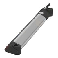
BMP 01-EL1PP21A-0128-00-P00,5-S75
Balluff BMP 01-EL1PP21A-0128-00-P00,5-S75 Manuels
Manuels et Guides d'utilisation pour Balluff BMP 01-EL1PP21A-0128-00-P00,5-S75. Nous avons
1
Balluff BMP 01-EL1PP21A-0128-00-P00,5-S75 manuel disponible en téléchargement PDF gratuit: Notice D'utilisation
Balluff BMP 01-EL1PP21A-0128-00-P00,5-S75 Notice D'utilisation (292 pages)
Marque:
Balluff
| Catégorie:
Capteurs
| Taille: 11.51 MB
Table des Matières
Deutsch
5
Table des Matières
5
Zulassungen und Kennzeichnungen
7
Verwendete Abkürzungen
7
Benutzerhinweise
7
Lieferumfang
7
Verwendete Symbole und Konventionen
7
Sicherheit
8
Bestimmungsgemäße Verwendung
8
Allgemeines zur Sicherheit
8
Bedeutung der Warnhinweise
8
Entsorgung
8
Aufbau und Funktion
9
Aufbau
9
Funktion
9
LED-Anzeige
10
IO-Link-Schnittstelle
10
Analog- und Schaltausgang
10
Einbau und Anschluss
11
Montage an einem Pneumatikzylinder mit T- oder C-Nut
12
Montage an einem Rundzylinder
13
Montage mit Freiem Positionsgeber
14
Elektrischer Anschluss
15
Kabelverlegung
15
Hinweise zum Betrieb
16
Inbetriebnahme
16
System in Betrieb Nehmen
16
Analoge Schnittstelle und Schaltausgang
17
Spannungsausgang 0
17
Stromausgang 4
17
Schaltausgang
17
Einstellungen über den Taster
17
IO-Link-Schnittstelle
19
Prozessdaten (PD)
20
Identifikationsdaten
21
Systembefehle
22
Messwertkonfiguration (MDC)
24
Ausgangskonfiguration
26
Diagnoseunterdrückung
26
Temperaturerfassung
27
Schwellenwerte für die Temperaturwarnung
27
Betriebsstundenzähler
27
Bootzykluszähler
27
Geräte-Fehlermeldungen
30
Technische Daten
31
Ausgang / Schnittstelle
31
Mechanische Daten
31
Anzeigen
31
Erfassungsbereich/Messbereich
31
Elektrischer Anschluss
31
Umgebungsbedingungen
31
Spannungsversorgung (Extern)
31
Zubehör
32
Positionsgeber BAM TG-MP
32
Montageset für T-Nut (BAM MC-MP-056-01-2-T5)
32
Montageset für C-Nut (BAM MC-MP-056-01-2-C3)
32
Halter für Rundzylinder (BAM MC-MP-054-01-R)
32
Schlauchschellen zur Befestigung der Halter
32
Typenschlüssel
33
Anhang
34
Typenschild
34
English
37
Abbreviations
39
Approvals and Markings
39
Notes to the User
39
Scope of Delivery
39
Symbols and Conventions
39
Disposal
40
Explanation of the Warnings
40
General Safety Notes
40
Intended Use
40
Safety
40
Construction and Function
41
Function
41
Analog and Switching Output
42
IO-Link Interface
42
LED Display
42
Installation and Connection
43
Mounting to a Pneumatic Cylinder Using a T- or C-Slot
44
Mounting to a Round Cylinder
45
Mounting with Floating Target
46
Electrical Connection
47
Cable Routing
47
Operating Notes
48
Starting up the System
48
Startup
48
Analog Interface and Switching Output
49
Current Output 4
49
Settings Using the Button
49
Switching Output
49
Voltage Output 0
49
Communication Parameters
51
IO-Link Interface
51
Process Data (PD)
52
Identification Data
53
System Commands
54
Measurement Value Configuration (MDC)
56
Diagnostic Suppression
58
Output Configuration
58
Boot Cycle Counter
59
Data Storage
60
Diagnostic Parameters
61
Operating Hours Counter
59
Temperature Detection
59
Threshold Values for the Temperature Warning
59
Device Error Messages
62
Ambient Conditions
63
Detection Range/Measuring Range
63
Displays
63
Electrical Connection
63
Mechanical Data
63
Output / Interface
63
Supply Voltage (External)
63
Technical Data
63
Accessories
64
BAM TG-MP-028 Magnet
64
Holders for Round Cylinders (BAM MC-MP-054-01-R)
64
Hose Clamps for Attaching the Holder
64
Mounting Set for C-Slot (BAM MC-MP-056-01-2-C3)
64
Mounting Set for T-Slot (BAM MC-MP-056-01-2-T5)
64
Type Code
65
Appendix
66
Part Label
66
Français
69
Abréviations Utilisées
71
Fourniture
71
Guide D'utilisation
71
Homologations et Certifications
71
Symboles et Conventions Utilisés
71
Elimination des Déchets
72
Généralités Sur la Sécurité
72
Signification des Avertissements
72
Sécurité
72
Utilisation Conforme aux Prescriptions
72
Fonction
73
Structure et Fonction
73
Affichage à LED
74
Interface IO-Link
74
Sorties Analogique et Sortie TOR
74
Montage et Raccordement
75
Limitations de Fonctionnement
75
Montage et Raccordement (Suite)
76
Montage Sur un Vérin Pneumatique Avec Rainure en T ou en C
76
Montage Sur un Vérin Cylindrique
77
Montage Avec un Capteur de Position Libre
78
Pose des Câbles
79
Raccordement Électrique
79
Conseils D'utilisation
80
Mise en Service du Système
80
Interface Analogique et Sortie de Commutation
81
Réglages Via le Bouton-Poussoir
81
Interface Analogique et Sortie de Commutation (Suite)
82
Fonctionnement Normal
82
Sortie Courant 4
81
Sortie de Commutation
81
Sortie Tension 0
81
Interface IO-Link
83
Données de Processus (PD)
84
Données D'identification
85
Ordres Système
86
Configuration des Valeurs Mesurées (MDC)
88
Configuration du Signal de Commutation (SSC)
89
Compteur D'heures de Service
91
Compteur de Cycles de Démarrage
91
Mesure de la Température
91
Valeurs Seuils pour L'avertissement de Température
91
Messages D'erreur de L'appareil
94
Affichages
95
Alimentation Électrique (Externe)
95
Caractéristiques Mécaniques
95
Caractéristiques Techniques
95
Conditions Ambiantes
95
Raccordement Électrique
95
Sortie / Interface
95
Zone de Détection / Plage de Mesure
95
Accessoires
96
Capteurs de Position BAM TG-MP
96
Kit de Montage pour Rainure en T (BAM MC-MP-056-01-2-T5)
96
Colliers de Serrage pour la Fixation des Supports
96
Support pour Vérin Cylindrique (BAM MC-MP-054-01-R)
96
Code de Type
97
Annexe
98
Plaque Signalétique
98
Italiano
101
Abbreviazioni Utilizzate
103
Autorizzazioni E Contrassegni
103
Avvertenze Per L'utente
103
Dotazione
103
Simboli E Segni Utilizzati
103
Informazioni DI Sicurezza
104
Significato Delle Avvertenze
104
Smaltimento
104
Utilizzo Conforme
104
Configurazione E Funzionamento
105
Funzione
105
Interfaccia IO-Link
106
Indicatore LED
106
Montaggio E Collegamento
107
Montaggio Su un Cilindro Pneumatico con Scanalatura a T O a C
108
Montaggio Su un Cilindro Circolare
109
Montaggio con Datore DI Posizione Libero
110
Collegamento Elettrico
111
Posa Dei Cavi
111
Avvertenze Per Il Funzionamento
112
Messa in Funzione
112
Messa in Funzione del Sistema
112
Impostazioni Tramite Il Pulsante
113
Interfaccia Analogica E Uscita DI Commutazione
113
Uscita DI Commutazione
113
Uscita DI Corrente 4
113
Uscita DI Tensione 0
113
Dati DI Processo (PD)
116
Dati Identificazione
117
Comandi DI Sistema
118
Dati Parametrici
119
Configurazione Dei Valori DI Misurazione (MDC)
120
Configurazione del Segnale DI Commutazione (SSC)
121
Indagine Diagnostica
122
Contaore D'esercizio
123
Contatore DI Cicli Boot
123
Rilevamento Temperatura
123
Valori Soglia Per Avviso DI Temperatura
123
Dati DI Diagnosi
125
Lista Event
125
Parametri Diagnostici
125
Messaggi DI Errore Dell'apparecchio
126
Campo DI Rilevamento / Campo DI Misurazione
127
Collegamento Elettrico
127
Condizioni Ambientali
127
Dati Meccanici
127
Dati Tecnici
127
Indicazioni
127
Tensione DI Alimentazione (Esterna)
127
Uscita / Interfaccia
127
Accessori
128
Datore DI Posizione BAM TG-MP
128
Fascette Per Il Fissaggio Dei Supporti
128
Supporti Per Cilindri Circolari (BAM MC-MP-054-01-R)
128
Legenda Codici DI Identificazione
129
Appendice
130
Targhetta DI Identificazione
130
Español
133
Abreviaturas Utilizadas
135
Homologaciones E Identificaciones
135
Indicaciones para el Usuario
135
Símbolos y Convenciones Utilizados
135
Volumen de Suministro
135
Eliminación de Desechos
136
Generalidades sobre la Seguridad
136
Seguridad
136
Significado de las Advertencias
136
Utilización Conforme al Uso Previsto
136
Estructura y Funcionamiento
137
Función
137
Indicador LED
138
Salida Analógica y Salida de Conmutación
138
Interfaz IO-Link
138
Montaje y Conexión
139
Montaje en un Cilindro Neumático con Ranura en T O en C
140
Montaje en un Cilindro Redondo
141
Montaje con Sensor de Posición Libre
142
Conexión Eléctrica
143
Tendido de Cables
143
Indicaciones sobre el Servicio
144
Puesta en Servicio del Sistema
144
Ajustes con la Tecla
145
Interfaz Analógica y Salida de Conmutación
145
Salida de Corriente 4
145
Salida de Tensión 0
145
Datos de Proceso (PD)
148
Datos de Identificación
149
Comandos del Sistema
150
Datos de Parámetros
151
Configuración de Valor de Medición (MDC)
152
Supresión del Diagnóstico
154
Captación de Temperatura
155
Contador de Ciclos de Arranque
155
Bloqueos de Acceso (Device Access Locks)
156
Estructura de Los Datos de Proceso (PD Input Descriptor)
156
Perfiles y Funciones (Profilecharacteristic)
156
Datos de Diagnóstico
157
Parámetros de Diagnóstico
157
Contador de Horas de Servicio
155
Valores Umbral para el Aviso de Temperatura
155
Mensajes de Error de Dispositivos
158
Alimentación de Tensión (Externa)
159
Conexión Eléctrica
159
Condiciones Ambientales
159
Datos Técnicos
159
Indicadores
159
Zona de Captación/Zona Medible
159
Abrazaderas de Manguera para Fijar Los Soportes
160
Accesorios
160
Sensor de Posición BAM TG-MP
160
Soportes para Cilindros Redondos (BAM MC-MP-054-01-R)
160
Código de Modelo
161
Anexo
162
Placa de Características
162
Português
165
Abrangência Do Fornecimento
167
Abreviaturas Utilizadas
167
Avisos a Usuários
167
Certificações E Caracterizações
167
Símbolos E Convenções Empregados
167
Eliminação
168
Informações Gerais de Segurança
168
Segurança
168
Significado Dos Avisos de Advertência
168
Utilização Conforme Programado
168
Função
169
Montagem
169
Montagem E Função
169
Lâmpada LED
170
Saídas Analógica E de Comutação
170
Instalação E Ligação
171
Montagem sobre um Cilindro Pneumático Com Ranhura T ou C
172
Montagem sobre um Cilindro Redondo
173
Montagem Com Indicador de Posição Livre
174
Avisos sobre O Funcionamento
176
Inicialização Do Sistema
176
Interface Analógica E Saída de Comutação
177
Saída de Corrente 4
177
Funcionamento Normal
178
Dados de Identificação
181
Dados de Parâmetros
183
Dados de Diagnóstico
189
Parâmetros de Diagnóstico
189
Lista de Eventos
189
Conexão Elétrica
191
Condições Ambientais
191
Placa de Identificação
194
Saída de Tensão 0
177
汉语
197
使用的缩写
199
供货范围
199
所使用的符号和惯例
199
用户提示 适用性
199
认证和标志
199
安全性 按规定使用
200
安全概述
200
废弃处理
200
警告提示的意义
200
结构与功能
201
Led 显示
202
模拟和开关输出端
202
安装和连接
203
安装到带T形槽或C形槽的气动缸上
204
安装到圆形气缸上
205
搭配自由的位置指示器安装
206
调试运行 系统投入使用
208
运行说明
208
开关输出端
209
电压输出0
209
日本語
229
使用されている省略形
231
利用者情報
231
同梱品
231
本書で使用するマークと決まりごと
231
認証と認証マーク
231
安全に関する一般事項
232
安全性
232
警告表示の説明
232
構造と機能
233
Led 表示
234
アナログ出力とスイッチング出力
234
IO-Link インタフェース
234
取付けと接続
235
T スロットまたは C スロット付きエアシリンダへの取付け
236
ラウンドシリンダへの取付け
237
浮動式ポジションエンコーダの取付け
238
ケーブルの配線
239
電気接続
239
セットアップ
240
操作時の注意
240
アナログインタフェースおよびスイッチング出力
241
スイッチング出力
241
ボタンでの調整
241
Руководство По Эксплуатации
259
Сфера Действия
263
Используемые Символы И Условные Обозначения
263
Объем Поставки
263
Разрешения И Маркировки
263
Используемые Сокращения
263
Использование По Назначению
264
Принцип Действия
265
Монтаж И Подключение
267
Ввод В Эксплуатацию Системы
272
Указания По Эксплуатации
272
Интерфейс IO-Link
275
Данные Процесса (PD)
276
Системные Команды
278
Условия Окружающей Среды
287
Напряжение Электропитания (Внешнего)
287
Заводская Табличка
290
電流出力 4~20 Ma
241
Publicité
Publicité
Produits Connexes
Balluff BMP 01-EL1PP21A-0096-00-P02
Balluff BMP 01-EL1PP21A-0032-00-P00,5-S75
Balluff BMP 01-EL1PP21A-0256-00-P00,5-S75
Balluff BMP 01-EL1PP21A-0032-00-P02
Balluff BMP 01-EL1PP21A-0192-00-P00,5-S75
Balluff BMP 01-EL1PP21A-0256-00-P02
Balluff BMP 01-EL1PP 1A 00-P S75 Série
Balluff BFT - 002- A1A- Série
Balluff BFF 004 A2C-S4 Série
Balluff BTL7-A 0-M K8-SA262-F Serie
Balluff Catégories
Capteurs
Équipement industriel
Transducteurs
Appareils de mesure
Unités de contrôle
Plus Manuels Balluff
Connexion
Se connecter
OU
Se connecter avec Facebook
Se connecter avec Google
Télécharger le manuel
Télécharger depuis le disque dur
Télécharger depuis l'URL