Chapitres
Table des Matières

Manuels Connexes pour Sony SMO-S551

Sommaire des Matières pour Sony SMO-S551
- Page 1 3-862-812-16(1) SMO-S551 5.25" Magneto-Optical Disk Subsystem 取扱説明書 ────────────── ページ User’s Guide page 16 ─────────── Mode d’emploi page 31 ───────── Bedienungsanleitung ──── Seite 45...
-
Page 2: Table Des Matières
目次 第1章 概要 5.25" 光磁気ディスクサブシステムについて ..特 長 ............4 使用できるディ スク ........5 システム構成 ..........5 各部の名称と働き ..........第2章 準備 付属品の確認 ............接続のしかた ............SCSI ID の設定 ..........サブシステムの機能の設定 ......... 第3章 使いかた ディスクの入れかた ......... ディスクの取り出しかた ........第4章 取り扱いについて サブシステムの取り扱い ........安全にお使いいただく ために ..... 12 万一の故障を防ぐために... - Page 3 説明書の使いかた ご注意 この取扱説明書は、 5.25" 光磁気ディスクサブシステ ム本体 (以下、 サブシステム) の使いかたと取り扱い • 本製品を日本国以外でご使用の場合は、必ずその 方法について説明しています。サブシステムをお使 国の電気事情にあった電源コー ドをご使用く ださい。 いになる前に、 必ずお読みく ださい。 お読みになった • 本製品の故障、 またはその使用により生じた損害に あとは、後日お役に立つこともありますので、保存し つきま しては、当社は責任を負いかねますので、 ご ておいてく ださい。 了承く ださい。 • 当社では本製品を使用して保存したデータの保証は この説明書は、 次の5つの章で構成されています。 目 いたしかねます。万一に備え、重要なデータはあら 的に合わせて、お読みく ださい。 かじめバックアップしておく ことをおすすめします。 •...
-
Page 4: 光磁気ディスクサブシステムについて
第1章 概要 5.25" 光磁気ディスクサブシステムについて □ インターフェースには、 SCSI-2 (Small Computer 特長 System Interface-2) を採用しています。 □ 高速スピンドルモーター 3300 min (rpm) によ 5.25"光磁気ディスクサブシステム本体には、 次のよ り、 2.48 〜 5.07 Mbytes/s(2048 bytes/sector うな特長があります。 時) 、 2.31 〜 4.79 Mbytes/s (1024 bytes/sector □ 光磁気記録方式により、何度でもデータの書き 時) または 1.97 〜 4.06 Mbytes/s(512 bytes/ 込み、消去ができます。... -
Page 5: 使用できるディスク
使用できるディスク このサブシステムでは、 ISO 準拠 130 mm (5.25 型) カー ト リ ッジ付両面光磁気ディスクが使用できます。 規格 セクターフォーマット ※ 容量 ISO/IEC 15286 2048 bytes/sector 約 5.2 Gbytes ISO/IEC 15286 1024 bytes/sector 約 4.8 Gbytes ISO/IEC 15286 512 bytes/sector 約 4.1 Gbytes ISO/IEC 14517 1024 bytes/sector R/W (DW) 約... -
Page 6: 各部の名称と働き
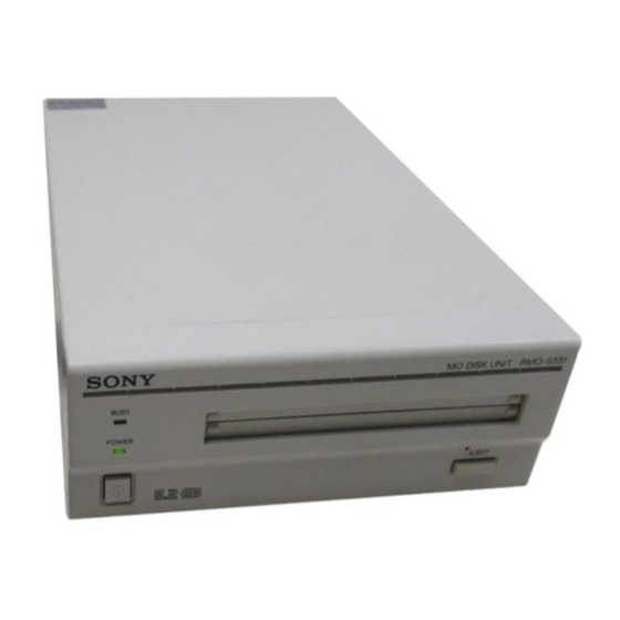
各部の名称と働き 前面 後面 B C D E F G H AC IN BUSY SCSI ID POWER SCSI CONNECTOR F.GND EJECT 1 2 3 POWERスイ ッチ 機能スイッチ 電源を入れたり切ったり (オン/オフ) するときに 使用するホス トコンピューターやソフ トウェアに合 押します。 ボタンが奥に引っ込んでいる状態がオ わせて、 サブシステムの機能を設定します。 詳し ン、出ている状態がオフです。 く は、 9 ページをご覧く ださい。 POWER (電源)... -
Page 7: 付属品の確認
第2章 準備 付属品を確認してから、サブシステムをホス トコン わったら、 SCSI IDスイ ッチでSCSI IDを選択し、 機能 ピューターやSCSI 周辺機器に接続します。接続が終 スイ ッチでサブシステムの機能を設定します。 付属品の確認 梱包を開いたら、サブシステムおよび下記の付属品 □ 5.25" 光磁気ディスクサブシステム本体 がそろっているか確認してく ださい。不足しているも □ 電源コー ド のがあったり、 何らかの損傷がある場合には、 お買い □ 手動イジェク ト用治具 上げの販売代理店にご連絡く ださい。 □ 取扱説明書 (本書) □ 取扱説明書 (安全のために) □ 投げ込み (LVD) 5.25"... -
Page 8: 接続のしかた
接続のしかた SCSIバスを通して、 1 台のホス トコンピューターに 7 台 • サブシステムをSCSI デイジーチェーンの最後に接 までの SCSI 周辺機器をつなぐことができます。 続する場合は、 後面の機能スイッチのFを 「 1 」 に設 定し、内蔵ターミネーターをオンにしてく ださい。そ ご注意 れ以外の場合は、 「 0 」 に設定し内蔵ターミネーター • 接続する前に必ずホス トコンピューター、サブシス をオフにしておきます。 テムおよび他の機器の電源を切ってく ださい。 •1台のホス トコンピューターに接続するSCSI ケーブ ルの合計の長さは、 6 m 以内にしてく ださい。 5.25"... -
Page 9: サブシステムの機能の設定
サブシステムの機能の設定 後面の機能スイ ッチ (A〜H) で、 使用するホス トコン キャ ッシュメモリー内のすべてのデータがディスクに ピューターやソフ トウェアに合わせてサブシステムの 書き込まれる前に電源を切るとデータが失われます。 機能を設定します。 サブシステムの電源を切るときは、 必ず使用中のディ 機能スイッチの切り替えは、サブシステムの電源を スクをイジェク ト してください。イジェク ト操作により 切ってから行ってく ださい。 データはディスク上に記録されます。 また、 ドライブが周期的にキャ ッシュメモリーのデータ B C D E F G H をディスクに一括書き込みをしていても、 停電が起き た場合はデータが失われる可能性があります。 Fast SCSI ■ ご注意 について... -
Page 10: 第3章 使いかた
第3章 使いかた ディスクの入れかた 画面左側にあるPOWERスイ ッチを押します。 ホス トコンピューター上でソフ トウェアを使って、 電源が入り、 POWERインジケーターが点灯しま ディスク上のデータを読み取ったり、 書き込んだ す。 り します。 データの読み取り ・書き込み中は、 BUSYインジ ケーターが橙色に点灯します。 ■ サブシステムが動作しない場合は サブシステム内が規定温度以上になると、読み書き の動作に関係なくBUSYインジケーターが約2秒ごと についたり消えたりを繰り返し、 サブシステムが動作 しなく なります。 この場合、空気の流通の良いところ に設置しなおしてく ださい。それでも動作しないとき は、電源コー ドをコンセン トから抜き、お買い上げの ホス トコンピューターを起動します。 販売代理店にご相談く ださい。 起動のしかたは、ホス トコンピューターに付属の 説明書をご覧く ださい。 使用する面を上にして、... -
Page 11: ディスクの取り出しかた
ディスクの取り出しかた ■ ディスクが取り出せない場合は イジェク トコマンドを使うか、 EJECT ボタンを押しま す。 次のような場合は、 EJECT ボタンを押したり、イジェ ク トコマン ドを使ってもディスクが取り出せないことが あります。 □ 機能スイ ッチやソフ トウェアでディスクのイジェク トが無効に設定されているとき □ ホス トコンピューターに トラブルが生じたとき □ 停電などで、 サブシステムの電源が入らないとき □ サブシステムが故障したとき EJECTボタンやソフ トウェアを使ってもディスクが取 り出せない場合は、 次のようにしてディスクを取り出し ご注意 ます。 ディスクのデータの読み書きによりBUSYインジケー サブシステムが接続されているホス トコンピュー ターが橙色に点灯している間 (内部温度上昇によりつ ターのシステムを終了してく... -
Page 12: 第4章 取り扱いについて
第4章 取り扱いについて サブシステムの取り扱い ■ 設置方向 安全にお使いいただくために このサブシステムは水平位置で使用してく ださ 別冊の 「安全のために」 もよくお読みのうえ、 製品を い。 安全にお使いく ださい。 ■ 設置場所 ■ 電源 次のような場所で、使用したり保管しないでく だ □ 日本国内では、 AC100 V でお使いく ださい。 さい。 □ 複写機やシュ レッダーのような消費電力の大 □ 湿気の多い所 きい機器と同じコンセン トから、 電源をとらな □ ほこりの多い所 いでく ださい。 □ 温度の高い所 □ 直射日光の当たる所... -
Page 13: その他ご注意いただきたいこと
■ ディスクを入れたまま移動しないでくだ ■ キャビネットが汚れたら さい キャビネッ トの汚れは、 乾いた柔らかい布で拭き 使わないときは、 ディスクを必ず取り出しておい とってく ださい。 汚れがひどいときは、 うすい中性 てく ださい。 ディスクを入れたまま、 サブシステム 洗剤溶液を少し含ませた布でふきと り、 乾いた布 を持ち運ばないでく ださい。 でからぶき してく ださい。 アルコール・ シンナー・ また、 使用中は、 ディスクが高速で回転していま 殺虫剤など、 揮発性の溶液剤は、 使用しないでく す。 このとき、サブシステムを動かすと、 動作が ださい。 表面の仕上げをいためたり、 表示が消え 不安定になったり、... -
Page 14: ディスクの取り扱い
ディスクの取り扱い • ほこ りやちりの多い所 取り扱い上のご注意 • 直射日光の当たる所 • 暖房器具の近く □ ディスクに激しい振動を与えたり、 落と したり しな • 湿気の多い所 いでく ださい。 □ ディスクカー ト リ ッジは、工場出荷時に精密に調 整されていますので、分解しないでく ださい。 □ ディスクカー ト リ ッジは、 サブシステムに挿入する ディスクのデータを守るために と、自動的にシャッターが開く自動装填式です。 カー ト リ ッジのシャ ッターを手で開けて、 内部に触 ディスクカー ト リ ッジには、 ディスクのデータを誤って れないでく... -
Page 15: 主な仕様
付録 主な仕様 バース ト転送速度 サブシステム 最大 5 Mbytes/s (同期転送) ■ 性能 最大 10 Mbytes/s (Fast SCSI 使用時) フォーマッ ト容量 ホス ト イ ンターフェース ディ スク当たり SCSI-2 (Small Computer System Interface-2) 5.2 Gbytes (ZCAV 2048 bytes/ ANSI X3.131-1994 sector) 4.8 Gbytes (ZCAV 1024 bytes/ ■... -
Page 16: Safety Regulations
Refer servicing Model No. SMO-S551 to qualified personnel only. Serial No._________________________ CAUTION As the laser beam used in the SMO-S551 is Information harmful to the eyes, do not attempt to disassemble the unit. For the customer in the U.S.A. - Page 17 According to the EU Directives related to On the Subsystem ........27 product safety, EMC and R&TTE the Safety Considerations ....... 27 manufacturer of this product is Sony Damage Prevention ........27 Corporation, 6-7-35 Kitashinagawa Other Points Requiring Attention ..... 28 Shinagawa-ku Tokyo, 141-0001 Japan.
-
Page 18: Using This Guide
Using this Guide This guide covers the use and operation of the Notes SMO-S551 Magneto-Optical Disk Subsystem • When using this product, make sure that the (called the “subsystem” thereafter). Do not power cord meets the electrical requirements of attempt to use the subsystem without first the country of use. -
Page 19: Chapter 1 Introduction
Features Computer System Interface-2). • The 3,300 min (3,300 rpm) high-speed spindle The SMO-S551 Magneto-Optical Disk motor enables data transfer rates of 2.48 – 5.07 Subsystem has the following features: Mbytes/s (2,048 bytes/sector), 2.31 – 4.79 • Magneto-optical technology enables repeated Mbytes/s (1,024 bytes/sector) or 1.97 –... -
Page 20: Compatible Disks
System Configuration linked in a daisy chain on the SCSI bus, and controlled with SCSI-2 commands. The subsystem should be used with a host computer equipped with SCSI. Host computer SCSI cable SMO-S551 subsystem SCSI peripheral devices Chapter 1 Introduction... -
Page 21: Location And Function Of Parts
Location and Function of Parts Front Panel Rear Panel B C D E F G H AC IN SCSI ID BUSY POWER SCSI CONNECTOR F.GND EJECT 1 2 3 Function switches POWER switch Use this switches to set the subsystem’s Push the button to turn the power on and off. -
Page 22: Chapter 2 Getting Started
Chapter 2 Getting Started Before setting up your SMO-S551 Magneto- may be using. After checking to see that all the Optical Disk Subsystem, check to see that you connections have been properly made, set the have all the required components and accessories. -
Page 23: Connecting The Subsystem
• The total length of the SCSI cables connected to the SCSI chain. a SCSI chain must not exceed six meters (19 feet 8 1/4 inches). SMO-S551 Magneto-Optical Disk Subsystem B C D E F G H AC IN SCSI ID SCSI CONNECTOR F.GND... -
Page 24: Setting The Subsystem's Functions
Setting the Subsystem’s Functions ■ Write Cache Precautions Use function switches (A – H) on the rear panel to select the subsystem’s functions in accordance This subsystem is equipped with a write cache. with the host computer and software you are When the write cache is enabled, never turn off using. -
Page 25: Chapter 3 Using The Subsystem
Chapter 3 Using the Subsystem Inserting a Disk Cartridge Press the POWER switch located on the left Access or write data on the disk using side of the front panel. software commands on the host computer. This turns on the subsystem and causes the The BUSY indicator lights up while the unit POWER indicator to light up. -
Page 26: Ejecting A Disk Cartridge
Ejecting a Disk Cartridge Eject the disk cartridge either by using software When you cannot eject the disk cartridge using commands or by pressing the EJECT button. the EJECT button or software commands, remove it as follows. Turn off the host computer connected with the subsystem. -
Page 27: Chapter 4 Precautions
Chapter 4 Precautions On the Subsystem ■ Location requirements Safety Considerations Careful consideration should be given to the ■ Power supply following in selecting a site to install or store your subsystem. • Be sure to use 100 - 240 V AC. Avoid the following conditions: •... -
Page 28: Other Points Requiring Attention
■ Moving the subsystem Other Points Requiring Attention Be sure to remove the disk cartridge when the subsystem is not being used. Also never move or ■ Electrical noise transport the unit with the disk cartridge still inserted. The high-frequency signal generated by the While in operation, the disk rotates at a high subsystem may cause interference or static on speed. -
Page 29: Protecting Your Data
Make it a practice to leave the write protection Protecting Your Data enabled when you do not foresee the need to write on the disk. The magneto-optical disk cartridges are equipped with a DATA PROTECT switch (red tab) to prevent accidental erasure of data on the disk or inadvertent writing of unwanted data. -
Page 30: Appendix
Appendix Specifications Host interface Subsystem SCSI-2 (Small Computer System Interface-2) ANSI X3.131–1994 ■ Performance ■ Operating environment Capacity (formatted) Per disk Installation 5.2 Gbytes (ZCAV 2,048 bytes/ Horizontal (±5°) sector) Temperature 4.8 Gbytes (ZCAV 1,024 bytes/ Operating sector) 5 °C to 40 °C (41 °F to 104 °F) 4.1 Gbytes (ZCAV 512 bytes/ (gradient 10°... -
Page 31: Règles De Sécurité
Règles de sécurité Sommaure Comment utiliser ce Guide ..... 32 AVERTISSEMENT Afin de réduire les risques d’incendie ou Chapitre 1 Introduction de choc électrique, n’exposez pas cet appareil à la pluie ni à l’humidité. Aperçu ............33 Pour éviter toute électrocution, ne pas Caractéristiques ........ -
Page 32: Comment Utiliser Ce Guide
Comment utiliser ce Guide Ce guide couvre l’emploi et le fonctionnement du Remarques sous-système de disque magnéto-optique SMO- • Lors de l’utilisation de ce produit, s’assurer que S551 (appelé ici le sous-système). le cordon d’alimentation correspond aux Ne pas essayer d’utiliser ce sous-système sans conditions du pays d’utilisation. -
Page 33: Chapitre 1 Introduction
• Le moteur à broche grande vitesse 3.300 min Le sous-système de disque magnéto-optique (3.300 tr/min.) permet la transmission des SMO-S551 possède les caractéristiques données à une vitesse de 2,48 - 5,07 Mo/s suivantes: (2.048 octets/secteur), 2,31 - 4,79 Mo/s (1.024 •... -
Page 34: Disques Compatibles
Sept périphériques maximum peuvent être reliés Configuration de système en chaîne sur le bus SCSI et contrôlés avec des instructions SCSI-2. Le sous-système doit être utilisé avec un ordinateur central équipé d’un SCSI. Ordinateur central Câble SCSI Sous-système SMO-S551 Périphériques SCSI Chapitre 1 Introduction... -
Page 35: Localisation Et Fonction Des Pièces
Localisation et fonction des pièces Panneau avant données de la mémoire-cache doivent d’abord être écrites sur la disquette. BUSY POWER EJECT Panneau arrière B C D E F G H AC IN SCSI ID Interrupteur d’alimentation (POWER) SCSI CONNECTOR F.GND Appuyer sur la touche pour mettre sous/hors tension. -
Page 36: Chapitre 2 Démarrage
Chapitre 2 Démarrage Avant l’implantation du sous-système de disque SCSI utilisés. Après la vérification des magnéto-optique SMO-S551, vérifier que tous connexions, régler les fonctions du les composants et accessoires requis sont sous-système et son adresse SCSI ID à l’aide disponibles. Puis, connecter le sous-système à... -
Page 37: Connexion Du Sous-Système
• La longueur totale des câbles SCSI connectés à une chaîne SCSI ne doit pas dépasser 6 mètres(19 pieds 8 pouces). Sous-système de disque magnéto-optique SMO-S551 B C D E F G H AC IN SCSI ID SCSI CONNECTOR F.GND... -
Page 38: Réglage Des Fonctions Du Sous-Système
Réglage des fonctions du sous-système ■ Précautions de cache d’écriture Sélectionner les fonctions du sous-système aux sélecteurs de fonction (A – H) du panneau Le sous-système est équipée d’une mémoire- arrière, selon l’ordinateur central et le logiciel cache d’écriture. Lorsque la mémoire-cache utilisés. -
Page 39: Chapitre 3 Fonctionnement Du Sous- Système
Chapitre 3 Fonctionnement du sous- système Insertion d’une cartouche disque Appuyer sur l’interrupteur POWER située Accéder ou écrire des données sur le disque sur le côtée gauche du panneau avant. Cela à l’aide d’instructions logicielles à met le lecteur sous tension et provoque l’ordinateur central. -
Page 40: Ejection D'une Cartouche Disque
Ejection d’une cartouche disque Ejecter la cartouche disque par instructions Procéder comme suit quand la cartouche disque logicielles ou en appuyant sur la touche EJECT. ne peut pas être ejectée en appuyant sur la touche EJECT ou en utilisant des instructions logicielles. Mettre l’ordinateur central raccordé... -
Page 41: Chapitre 4 Précautions
Chapitre 4 Précautions A propos du sous-système ■ Exigences concernant Sécurité l’emplacement ■ Alimentation Tenir compte des points suivants lors de la sélection de l’emplacement d’installation ou de • S’assurer d’utiliser du CA 100 - 240 V. stockage du lecteur. •... -
Page 42: A Propos Des Cartouches Disques
■ Déplacement du sous-système Autres points à prendre en compte Ne pas oublier de retirer la cartouche disque quand le sous-système n’est pas utilisé. Ne ■ Parasites jamais déplacer ou transporter l’appareil avec une cassette disque à l’intérieur. En fonctionnement, Le signal de hautes fréquences produit par le le disque tourne à... -
Page 43: Protection Des Données
S’habituer à laisser la protection contre Protection des données l’écriture validée quand on ne prévoit pas d’écrire sur le disque. Les cartouches disques magnéto-optiques sont équipées d’un curseur DATA PROTECT (ergot rouge) pour éviter tout effacement accidentel des données du disque ou écriture par inadvertance de données non souhaitées. -
Page 44: Appendice
Appendice Spécifications ■ Environnement de fonctionnement Sous-système Installation ■ Performances Horizontale (± 5°) Température Capacité (formaté) Fonctionnement Par disque 5 à 40 °C (41 à 104 °F) 5,2 Go (ZCAV 2048 octets/secteur) (gradient de 10 °C/h ou 18 °F/h) 4,8 Go (ZCAV 1024 octets/secteur) Non fonctionnement 4,1 Go (ZCAV 512 octets/secteur) –30 à... -
Page 45: Sicherheitsbestimmungen
Gerät benutzt PRODUKT wird. Im Sinne der EU Richtlinien bezüglich HINWEIS Produktsicherheit, EMV und R&TTE ist Sony Maschinenlärminformations-Verordnung - 3. Corporation, 6-7-35 Kitashinagawa GPSGV, der höchste Schalldruckpegel beträgt Shinagawa-ku Tokyo, 141-0001 Japan der 70 dB(A) oder weniger gemäß EN ISO 7779. - Page 46 Inhalt Verwendung dieses Handbuchs .... 47 Entsorgung von gebrauchten elektrischen und elektronischen Geräten (anzuwenden in den Ländern der Europäischen Union und anderen Kapitel 1 Einführung europäischen Ländern mit einem separaten Sammelsystem für diese Überblick ..........48 Geräte) Merkmale ..........48 Kompatible Disks ........
-
Page 47: Verwendung Dieses Handbuchs
Verwendung dieses Handbuchs Dieses Handbuch beschreibt den Betrieb und die Hinweise Bedienung des MO-Subsystems SMO-S551 • Achten Sie darauf, daß das Netzkabel den (nachfolgend Subsystem genannt). Lesen Sie elektrischen Anforderungen des Landes diese Anleitung bitte sorgfältig durch, bevor Sie entspricht, in dem dieses Gerät benutzt wird. -
Page 48: Kapitel 1 Einführung
Kapitel 1 Einführung Überblick • Das Subsystem benutzt SCSI-2 (Small Merkmale Computer System Interface-2). • Ein schneller Spindelmotor mit einer Drehzahl Das MO-Subsystem SMO-S551 bietet die von 3300 min ermöglicht folgenden Merkmale: Datentransfergeschwindigkeiten von 2,48 bis • Magnetooptische Technologie ermöglicht 5,07 MByte/s (2048 Byte/Sektor), 2,31 bis 4,79 wiederholtes Schreiben und Lesen von Daten. -
Page 49: Kompatible Disks
Kompatible Disks Das Subsystem arbeitet mit den folgenden 130 mm (5,25 Zoll) MO-Disks von Sony: Standard Sektor-Format Hinweise Kapazität ISO/IEC 15286 2048 Byte/Sektor Etwa 5,2 GByte ISO/IEC 15286 1024 Byte/Sektor Etwa 4,8 GByte ISO/IEC 15286 512 Byte/Sektor Etwa 4,1 GByte... -
Page 50: Lage Und Funktion Der Teile
Lage und Funktion der Teile Frontplatte Sekunden), bis die Disk ausgeworfen wird, weil die Daten im Cache zuerst auf die Disk BUSY geschrieben werden müssen. POWER EJECT Rückwand B C D E F G H AC IN SCSI ID POWER-Schalter SCSI CONNECTOR F.GND Zum Ein- und Ausschalten der Disk-Einheit. -
Page 51: Kapitel 2 Betriebsvorbereitungen
Kapitel 2 Betriebsvorbereitungen Bevor Sie mit dem Anschluß des MO- innerhalb Ihres Systems an. Vergewissern Sie Subsystems SMO-S551 beginnen, vergewissern sich von der Korrektheit aller Anschlüsse und Sie sich bitte davon, daß sämtliche erforderlichen stellen Sie danach die Funktionen und die SCSI- Komponenten und Zubehörteile bereitliegen. -
Page 52: Anschließen Des Subsystems
Funktionsschalter F auf “0” stehen. anderen Ausrüstungen in der SCSI-Verkettung • Die Gesamtlänge aller SCSI-Kabel in der SCSI- aus. Verkettung darf 6 Meter nicht überschreiten. MO-Subsystem SMO-S551 B C D E F G H AC IN SCSI ID SCSI CONNECTOR F.GND... -
Page 53: Einstellen Der Funktionen Des Subsystems
Einstellen der Funktionen des Subsystems ■ Vorsichtsmaßnahmen den Write- Mit den Funktionsschaltern A bis H an der Rückwand lassen sich die Funktionen des Cache betreffend Subsystems auf den Host-Rechner und die Dieses Subsystem ist mit einem Schreib-Cache jeweils verwendete Software einstellen. Schalten ausgestattet. -
Page 54: Kapitel 3 Bedienung
Indikator in 2-Sekunden-Intervallen an zu blinken, und der Betrieb des Subsystems stoppt. Sorgen Sie in diesem Fall für eine bessere Luftzirkulation am Aufstellungsort. Wenn dies nichts hilft, benachrichtigen Sie bitte Ihren Sony-Fachhändler. Power-Schalter drüken Starten Sie den Host-Rechner. Lesen Sie hierzu bitte die Bedienungsanleitung des Host-Rechners. -
Page 55: Auswerfen Einer Mo-Disk
Auswerfen einer MO-Disk Werfen Sie die MO-Disk entweder über Wenn sich die MO-Disk nicht durch Drücken der Softwarebefehl aus oder drücken Sie die EJECT- EJECT-Taste oder über Softwarebefehle Taste. auswerfen läßt, gehen Sie wie folgt vor: Schalten Sie den mit dem Subsystem verbundenen Host-Rechner aus. -
Page 56: Kapitel 4 Zur Besonderen Beachtung
Kapitel 4 Zur besonderen Beachtung Für das Subsystem ■ Zum Aufstellplatz Zur Betriebssicherheit Wählen Sie sowohl für den Betrieb als auch für ■ Netzversorgung die Aufbewahrung/Lagerung des Subsystems geeignete Plätze. • Nur 100 - 240 V Wechselstrom benutzen. Vermeiden Sie insbesondere Plätze, an denen die •... -
Page 57: Weitere Wichtige Punkte
■ Standortwechsel Weitere wichtige Punkte Entfernen Sie stets die MO-Disk aus einem nicht ■ Elektromagnetische Störfelder verwendeten Subsystem und/oder bevor Sie das Subsystem an einen anderen Aufstellplatz Das Subsystem erzeugt HF-Strahlen, die bewegen oder sonstwie transportieren. Eine möglicherweise den Rundfunk- und eingelegte MO-Disk wird mit hoher Drehzahl Fernsehempfang beeinträchtigen. -
Page 58: Datenschutz
Machen Sie es sich zur Regel, stets den Datenschutz Schreibschutz zu aktivieren, wenn Sie in absehbarer Zeit kein Schreiben mit der Die MO-Disk-Cartridges verfügen über einen betreffenden MO-Disk beabsichtigen. roten Schieber (DATA PROTECT), um ein unbeabsichtigtes Löschen oder Überschreiben von Daten zu verhindern. Verstellen Sie diesen Schieber nach links (siehe Abbildung), um den Schreibschutz zu aktivieren. -
Page 59: Anhang
Anhang Technische Daten ■ Umgebungsbedingungen Subsystem Aufstellung ■ Leistungswerte Waagerecht (± 5°) Temperatur Speicherkapazität (formatiert) Betrieb Je Disk 5 °C bis 40 °C (Anstieg 10 °C/Std.) 5,2 GByte (ZCAV 2048 Bytes/ Nichtbetrieb Sektor) – 30 °C bis 60 °C 4,8 GByte (ZCAV 1024 Bytes/ Feuchtigkeit Sektor) Betrieb... - Page 60 SMO-S551 5.25" Magneto-Optical Disk Subsystem 取扱説明書 User’s Guide Mode d’emploi Bedienungsanleitung Printed in Japan...