
Manuels Connexes pour Acson C Serie

Sommaire des Matières pour Acson C Serie
- Page 1 All manuals and user guides at all-guides.com INSTALLATION MANUAL INVERTER CEILING CONCEALED SPLIT TYPE AIR CONDITIONER (C Series) IM-5CCY-0709(1)-ACSON Part No.: R08019033602A...
- Page 2 All manuals and user guides at all-guides.com...
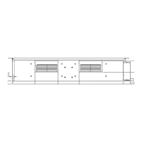
- Page 3 All manuals and user guides at all-guides.com OUTLINE AND DIMENSIONS Indoor Unit 5CCY10/15/20/25C/CR Dimension Model 5CCY10/15C/CR 261 411 351 225 211 232 1041 1002 1065 261 411 351 225 211 232 5CCY20C/CR 5CCY25C/CR 1175 1137 1097 1200 261 411 351 225 211 232 Indoor Unit 5CCY28/38CR All dimensions are in mm Dimension...
- Page 4 All manuals and user guides at all-guides.com Indoor Unit 5CCY50/60CR Dimension Model 1369 1326 1287 593.5 541 256 306 255.5 160.5 5CCY50CR 5CCY60CR 1569 1526 1487 693.5 541 256 306 355.5 160.5 Outdoor Unit 5SLY10/15D/DR Dimension Model 5SLY10/15D/DR 29.5 105.5...
- Page 5 All manuals and user guides at all-guides.com Outdoor Unit 5SLY20/25C/CR All dimensions are in mm Dimension Model 5SLY20/25C/CR Dimension Model 5SLY20/25C/CR Outdoor Unit 5SLY28CR Dimension Model 940 348 753 855 392 733 603 328 303 370 362 448 190 5SLY28CR...
- Page 6 All manuals and user guides at all-guides.com Outdoor Unit 5SLY40/50/60FR All dimensions are in mm Dimension Model 1374 5SLY40/50/60FR...
- Page 7 All manuals and user guides at all-guides.com INSTALLATION MANUAL This manual provides the procedures of installation to ensure a safe and good standard of operation for the air conditioner unit. Special adjustment may be necessary to suit local requirements. Before using your air conditioner, please read this instruction manual carefully and keep it for future reference. This appliance is intended to be used by expert or trained users in shops, in light industry and on farms, or for commercial use by lay persons.
- Page 8 All manuals and user guides at all-guides.com IMPORTANT Important information regarding the refrigerant used This product contains fl uorinated greenhouse gases covered by the Kyoto Protocol. Do not vent gases into the atmosphere. Refrigerant type: R410A value: 1975 GWP = global warming potential Please fi...
- Page 9 All manuals and user guides at all-guides.com INSTALLATION DIAGRAM Indoor Unit Hanger Return duct Supply duct Wrap the insulated pipe with the fi nishing tape from bottom to top Drain Thermal insulation piping Air Intake Air Intake Air Discharge Outdoor Unit...
- Page 10 All manuals and user guides at all-guides.com INSTALLATION OF THE INDOOR UNIT The indoor unit must be installed such that there is no short Center distance of axle (see drawing below) circuit of the cool discharge. Respect the installation clearance. Do not put the indoor unit where there is direct sunlight on unit.
- Page 11 All manuals and user guides at all-guides.com Ceiling Concealed Drain Piping Work Unit : mm • The drain pipe must be installed as shown in the diagram (see diagram above) to avoid damage caused by leaks and condensation. • For the best result, keep the piping as short as possible. Slant the piping at an angle to improve the fl ow. •...
- Page 12 All manuals and user guides at all-guides.com INSTALLATION OF THE OUTDOOR UNIT • The outdoor unit must be installed in such a way, so as to prevent short circuit of the hot discharged air or obstruction to the smooth air fl ow. Please follow the installation clearance shown in the fi gures below. Select the coolest possible place where intake air temperature is not greater than the outside air temperature.
- Page 13 All manuals and user guides at all-guides.com 5SLY40/50/60FR Wall facing one side More than 100 More than 500 Side View Wall facing more than 1 side of obstacle More More than 100 than More than 100 More than 100 More than 500 Unit: mm Top View •...
- Page 14 All manuals and user guides at all-guides.com REFRIGERANT PIPING Allowable Piping Length When the pipe length becomes too long, both the capacity and reliability drop. As a result, compressor reliability will be affected. Always choose the shortest path and follow the recommendation as tabulated below: Indoor 5CCY10C/CR 5CCY15C/CR 5CCY20C/CR 5CCY25C/CR 5CCY28CR Outdoor...
- Page 15 All manuals and user guides at all-guides.com Pipe Size, mm (in) Torque, Nm / (ft-lb) Fig. B 6.35 (1/4") 18 (13.3) 9.52 (3/8") 42 (31.0) 12.70 (1/2") 55 (40.6) Remove Burr 15.88 (5/8") 65 (48.0) 19.05 (3/4") 78 (57.6) Fig. D Flare Joint Fig.
- Page 16 All manuals and user guides at all-guides.com 5CCY28CR - 5SLY28CR Indoor Unit Outdoor Unit Terminal Block Terminal Block Interconnection cable Power Supply Cable There must be an all pole disconnection in the supply mains with a contact separation of at least 3mm. Model Indoor 5CCY28CR...
- Page 17 All manuals and user guides at all-guides.com 5CCY38CR - 5SLY40FR (3 Phase) 5CCY50/60CR - 5SLY50/60FR (3 Phase) Indoor Unit Outdoor Unit Terminal Block Terminal Block Interconnection Cable Power Supply Cable There must be an all pole disconnection in the supply mains with a contact separation of at least 3mm.
- Page 18 All manuals and user guides at all-guides.com • All wires must be fi rmly connected. • Make sure all the wire do not touch the refrigerant pipings, compressor or any moving parts. • The connecting wire between the indoor unit and the outdoor unit must be clamped by using provided cord anchorage. •...
- Page 19 All manuals and user guides at all-guides.com VACUUMING AND CHARGING Vacuuming is necessary to eliminate all moisture and air from the system. The series II Outdoor Unit is provided with fl are valve fi ttings. Vacuuming The Piping And The Indoor Unit Refrigerant Piping Allen key Flare nut...
- Page 20 All manuals and user guides at all-guides.com BELOW INFORMATION IS APPLICABLE FOR 5SLY40/50/60FR ONLY 1. Handling 5. Pump-down operation Never by-pass the low pressure switch or low pressure sensor during pump down operation. Power supply must be cut off before pump-down operation. After opening the front panel, cover the PCB and terminal board with insulation sheet to avoid electric shock by accidental touching of LIVE parts.
- Page 21 All manuals and user guides at all-guides.com OPERATING RANGE COOLING HEATING 14 15 19 20 INDOOR TEMP. WB (˚C) INDOOR TEMP. DB(˚C) DB: Dry bulb WB: Wet bulb 1-19...
- Page 22 All manuals and user guides at all-guides.com INDICATOR LIGHTS 5SLY28CR Fault Diagnosis The outdoor unit LED indicates the running condition of the system: LED INDICATION Green Description NORMAL INSTALLATION ERROR ANTIFREEZE (OTHER ROOMS) HEAT SINK OVERHEAT IPM ERROR/IGBT ERROR INSUFFICIENT GAS AC INPUT OVER CURRENT COMPRESSOR START-UP ERROR COMMUNICATION ERROR (OUTDOOR CONTROL PCB AND IPM PCB)
- Page 23 All manuals and user guides at all-guides.com CONTOUR ET DIMENSIONS Unité Intérieure 5CCY10/15/20/25C/CR Dimension Modèle 5CCY10/15C/CR 261 411 351 225 211 232 5CCY20C/CR 1041 1002 1065 261 411 351 225 211 232 5CCY25C/CR 1175 1137 1097 1200 261 411 351 225 211 232 Unité...
- Page 24 All manuals and user guides at all-guides.com Unité Intérieure 5CCY50/60CR Dimension Modèle 5CCY50CR 1369 1326 1287 593,5 306 255,5 160,5 248 5CCY60CR 1569 1526 1487 693,5 306 355,5 160,5 248 Unité Extérieure 5SLY10/15D/DR Dimension Modèle 5SLY10/15D/DR 29,5 105,5...
- Page 25 All manuals and user guides at all-guides.com Unité Extérieure 5SLY20/25C/CR Toutes les dimensions sont données en mm Dimension Modèle 5SLY20/25C/CR Dimension Modèle 5SLY20/25C/CR Unité Extérieure 5SLY28CR Dimension Modèle 5SLY28CR 940 348 753 855 392 733 603 328 303 370 362 448 190...
- Page 26 All manuals and user guides at all-guides.com Unité Extérieure 5SLY40/50/60FR Toutes les dimensions sont données en mm Dimension Modèle 1374 5SLY40/50/60FR...
- Page 27 All manuals and user guides at all-guides.com MANUEL DʼINSTALLATION Ce manuel fournit les procédures dʼinstallation pour assurer le bon fonctionnement et la sécurité de cet appareil. Des ajustements peuvent être nécéssaires pour suivre les réglementations locales. Avant dʼinstaller et de faire fonctionner le climatiseur, lisez attentivement ce manuel et conservez le. Cet appareil est destiné...
- Page 28 All manuals and user guides at all-guides.com IMPORTANT Information importante relative au réfrigérant utilisé Ce produit contient des gaz fl uorés à effet de serre encadrés par le protocole de Kyoto. Ne pas laisser les gaz sʼéchapper dans lʼatmosphère. Type de réfrigérant : R410A Valeur GWP 1975 GWP = potentiel de réchauffement global...
- Page 29 All manuals and user guides at all-guides.com DIAGRAMME DʼINSTALLATION Unité intérieure Étrier Conduit de reprise Conduit dʼalimentation Enveloppez le tuyau isolé de bande defi nition de bas en haut Tuyauterie Isolation thermique dʼévacuation Reprise Air Reprise Air Unité extérieure Refoulement dʼair...
- Page 30 All manuals and user guides at all-guides.com INSTALLATION DE LʼUNITÉ INTÉRIEURE Lʼunité intérieure doit être installée de façon à ce quʼil nʼy ait Distance centrale de lʼaxe (consulter le schéma ci-dessous) aucun court circuit de lʼair dʼévacuation froid. Respectez les dégagements minimums.
- Page 31 All manuals and user guides at all-guides.com Travaux de tuyauterie de vidange cachée dans le plafond Unité : mm • Le tuyau de vidange doit être installé comme indiqué dans le schéma (voir le diagramme ci-dessus) pour éviter les dommages causés par des fuites et la condensation.
- Page 32 All manuals and user guides at all-guides.com INSTALLATION DE LʼUNITÉ EXTÉRIEURE • Lʼunité extérieure doit être installée de manière à ce quʼil nʼy ait pas de reprise dʼair chaud ou dʼobstruction au débit régulier dʼair. Veuillez suivre les jeux de lʼinstallation illustrés sur les fi gures ci-dessous. Choisir lʼemplacement le plus frais possible, où...
- Page 33 All manuals and user guides at all-guides.com 5SLY40/50/60FR Mur face à un côté Plus de 100 Plus de 500 Vue latérale Mur face à plus dʼun côté de lʼobstacle Plus de Plus de 100 Plus de Plus de 100 Plus de 500 Unité...
- Page 34 All manuals and user guides at all-guides.com RACCORDEMENTS DES TUYAUTERIES Longueur admissible de tuyauterie Lorsque le conduit est trop long, la capacité et la fi abilité diminuent. En conséquence, la fi abilité du compresseur sʼen trouve affectée. Choisissez toujours le chemin le plus court et suivez les recommandations données dans le tableau ci-dessous : Intérieure 5CCY10C/CR 5CCY15C/CR 5CCY20C/CR 5CCY25C/CR 5CCY28CR Extérieure...
- Page 35 All manuals and user guides at all-guides.com Tuyau, mm (pouce) Couple, Nm Figure B 6,35 (1/4") 18 (13,3) 9,52 (3/8") 42 (31,0) 12,70 (1/2") 55 (40,6) Ebavurage 15,88 (5/8") 65 (48,0) 19,05 (3/4") 78 (57,6) Figure D Figure C Raccord à Visser Tube Avec Dudgeon Tube Cuivre Dudgeonniere...
- Page 36 All manuals and user guides at all-guides.com 5CCY28CR - 5SLY28CR Bornier de Bornier de lʼunité extérieure lʼunité intérieure Câble dʼinterconnexion Cordon Electrique Il doit y avoir une déconnexion de tour les pôles de lʼalimentation secteur avec une séparation des contacts dʼau moins 3 mm.
- Page 37 All manuals and user guides at all-guides.com 5CCY38CR - 5SLY40FR (3 Phase) 5CCY50/60CR - 5SLY50/60FR (3 Phase) Bornier de Bornier de lʼunité lʼunité intérieure extérieure Câble dʼinterconnexion Cordon Electrique Il doit y avoir une déconnexion de tour les pôles de lʼalimentation secteur avec une séparation des contacts dʼau moins 3 mm.
- Page 38 All manuals and user guides at all-guides.com • Tous les fi ls doivent être fermement connectés. • Aucun fi l électrique ne doit toucher ni la tuyauterie du réfrigérant, ni le compresseur, ni les pièces mobiles du moteur de ventilation. •...
- Page 39 All manuals and user guides at all-guides.com TIRAGE AU VIDE ET CHARGE Aspirer est nécessaire pour éliminer toute humidité et air du système. La série II Unité Extérieure est fournie avec des raccords de valve fl are. Aspiration sous vide des tuyauteries et de lʼunité Tuyauteries Frigorifi...
- Page 40 All manuals and user guides at all-guides.com LES INFORMATIONS CI-DESSOUS SʼAPPLIQUENT UNIQUEMENT AU MODÈLE 5SLY40/50/60FR 1. Manipulation 5. Opération de pump-down Ne jamais contourner le commutateur de basse pression ou le capteur de basse pression pendant lʼopération de pump- down. Lʼalimentation doit être coupée avant lʼopération de pumpdown.
- Page 41 All manuals and user guides at all-guides.com PLAGE DE FONCTIONNEMENT REFROIDISSEMENT CHAUFFAGE 14 15 19 20 TEMP. INT. WB (˚C) TEMP. INT. DB (˚C) DB: Thermomètre sec WB: Thermomètre mouillé 2-19...
- Page 42 All manuals and user guides at all-guides.com LʼINDICATEUR SʼALLUME 5SLY28CR Diagnostic dʼerreurs Le voyant DEL de lʼunité extérieure indique lʼétat de fonctionnement du système : INDICATION DEL Vert Rouge Description NORMAL ERREUR DʼINSTALLATION ANTIGEL (AUTRES PIÈCES) DISSIPATEUR THERMIQUE DE SURCHAUFFE ERREUR IPM / ERREUR IGBT INSUFFISANCE DE GAZ SURINTENSITÉ...
- Page 43 All manuals and user guides at all-guides.com AUSLEGUNG UND ABMESSUNGEN Innen-Gerät 5CCY10/15/20/25C/CR Abmessung Modell 5CCY10/15C/CR 5CCY20C/CR 31 1041 1002 10 1065 5CCY25C/CR 31 1175 1137 1097 10 1200 Innen-Gerät 5CCY28/38CR Alle Dimensionen sind in mm Abmessung Modell 5CCY28CR 1001 5CCY38CR 1306 1264 1225...
- Page 44 All manuals and user guides at all-guides.com Innen-Gerät 5CCY50/60CR Abmessung Modell 5CCY50CR 359 1369 1326 1287 593,5 541 256 173 306 255,5 160,5 248 5CCY60CR 359 1569 1526 1487 693,5 541 256 173 306 355,5 160,5 248 Außen-Gerät 5SLY10/15D/DR Abmessung Modell 5SLY10/15D/DR 29,5...
- Page 45 All manuals and user guides at all-guides.com Außen-Gerät 5SLY20/25C/CR Alle Dimensionen sind in mm Abmessung Modell 5SLY20/25C/CR Abmessung Modell 5SLY20/25C/CR Außen-Gerät 5SLY 28CR Abmessung Modell 5SLY28CR 940 348 753 855 392 733 603 328 303 370 362 448 190 80 58 180 32 126 32 15 23...
- Page 46 All manuals and user guides at all-guides.com Außen-Gerät 5SLY 40/50/60FR Alle Dimensionen sind in mm Abmessung Modell 1374 5SLY40/50/60FR...
- Page 47 All manuals and user guides at all-guides.com INSTALLATIONSHANDBUCH Das vorliegende Handbuch enthält die Installationsanweisungen für einen sicheren und ordnungsgemäßen Betrieb dieser Anlage. Je nach den örtlichen Gegebenheiten können spezielle Anpassungen notwendig sein. Vor der Inbetriebnahme des Klimagerätes dieses Handbuch bitte aufmerksam zur Kenntnis nehmen und für künftigen Bedarf aufbewahren.
- Page 48 All manuals and user guides at all-guides.com WICHTIG Wichtige Informationen hinsichtlich des verwendeten Kältemittels Dieses Produkt enthält fl uorierte Treibhausgase, die durch das Kyoto-Protokoll abgedeckt werden. Lassen Sie Gase nicht in die Atmosphäre ab. Kältemitteltyp: R410A Wert: 1975 GWP = Treibhauspotential Bitte füllen Sie das Etikett betr.
- Page 49 All manuals and user guides at all-guides.com INSTALATIONSDIAGRAMM Aufhänger Innen-Gerät Rücklaufkanal Zuführungskanal Umwickeln Sie die isolierte Rohrleitung von oben bis unten mit Finishingtape Ablassrohr Wärmeisolierung Lufteinlass Lufteinlass Luftauslaß Außen-Gerät...
- Page 50 All manuals and user guides at all-guides.com INSTALLATION DES INNENGERÄTES Die Inneneinheit muss so installiert werden, dass kein Achsabstand (siehe Zeichnung unten) Kurzschluss im Austrittskanal der Kühlluft entstehen kann. Bitte die Richtlinien für die Installation beachten. Die Inneneinheit nicht an einem Ort installieren, wo sie direktem Sonnenlicht ausgesetzt ist.
- Page 51 All manuals and user guides at all-guides.com Installation deckenintegrierter Ablassrohrleitungen Gerät: mm • Das Abfl ussrohr wie in der Abbildung (siehe oben) montieren, um Schäden, die durch Lecks und Kondenswasser entstehen, zu vermeiden. • Für beste Resultate, die Rohrleitungen so kurz wie möglich halten. Die Rohrleitungen sollten in einem Winkel ausgerichtet sein, um den Abfl...
- Page 52 All manuals and user guides at all-guides.com INSTALLATION DES AUßENGERÄTES • Das Außengerät ist so zu installieren, dass keine Interferenz zwischen der Abblasluft und der Umwälzluft bzw. kein Hindernis gegeben ist. Beachten Sie die Installationsabstände, wie in den Abbildungen unten angegeben. Wählen Sie den kühlsten Ort zur Installation, wo die Temperatur der angesaugten Luft nicht höher als die Außentemperatur.
- Page 53 All manuals and user guides at all-guides.com 5SLY40/50/60FR Wand an einer Seite Über 100 Über 500 Seitenansicht Hindernis an mehr als 1 Seite Über 100 Über 100 Über 100 Über 100 Über 500 Gerät: mm Draufsicht • Installieren Sie das Gerät mit einem zusätzlichen Abstand, wenn sich ein Hindernis an der Oberseite befi ndet, oder bei einem Reiheneinbau.
- Page 54 All manuals and user guides at all-guides.com KÜHLMITTELLEITUNG Erlaubte Leitungslänge Ist die Länge der Rohrleitungen zu lang, so sinkt sowohl die Kapazität als auch die Zuverlässigkeit. Dies führt dazu, dass die Effi zienz des Kompressors abnimmt. Immer den kürzesten Leitungsweg unter Beachtung nachstehender Empfehlungen wählen: Innen 5CCY10C/CR 5CCY15C/CR 5CCY20C/CR 5CCY25C/CR 5CCY28CR...
- Page 55 All manuals and user guides at all-guides.com Rohrgröße, mm (zoll) Anzugsmoment, Nm / (ft-lb) Abb. B 6,35 (1/4") 18 (13,3) 9,52 (3/8") 42 (31,0) Rohrentgratung 12,70 (1/2") 55 (40,6) 15,88 (5/8") 65 (48,0) 19,05 (3/4") 78 (57,6) Abb. C Abb. D Anzugsring Aufgeweitetes Rohr Kupferrohr...
- Page 56 All manuals and user guides at all-guides.com 5CCY28CR - 5SLY28CR Innen-Gerät Außen-Gerät Klemmenblock Klemmenblock Verbindungskabel Anschluss-Kabel In dem Hauptversorgungsnetz muss eine Unterbrechung aller Pole vorhanden sein, mit einem Kontaktunterbrecher von mindestens 3 mm. Modell Innen 5CCY28CR Außen 5SLY28CR Spannungsbereich** Innen 220V - 240V/1Ph/50Hz + ! Außen 220V - 240V/1Ph/50Hz + !
- Page 57 All manuals and user guides at all-guides.com 5CCY38CR - 5SLY40FR (3 Phase) 5CCY50/60CR - 5SLY50/60FR (3 Phase) Innen-Gerät Außen-Gerät Klemmenblock Klemmenblock Interconnection Verbindungskabel cable Power Supply Cable Anschluss-Kabel In dem Hauptversorgungsnetz muss eine Unterbrechung aller Pole vorhanden sein, mit einem Kontaktunterbrecher von mindestens 3 mm.
- Page 58 All manuals and user guides at all-guides.com • Alle Adern sind fest zu verdrahten. • Stellen Sie sicher, dass alle Kabel die Kältemittelleitungen, den Kompressor oder andere bewegliche Teile nicht berühren. • Der Verbindungsdraht zwischen dem Innen- und Außengerät muss durch die mitgelieferte Kabelbefestigung eingeklemmt werden.
- Page 59 All manuals and user guides at all-guides.com VAKUUMHERSTELLUNG UND LADEN Das Absaugen ist erforderlich, um alle eventuell im System vorhandene Feuchtigkeit und Luft zu entfernen. Das Außengerät der Baureihe II ist mit Ablaßventilen bestückt. Evakuierung der Leitung und des Innenmontagegeräts Gewinde- Kältemittel-leitung Sechskantsteckschlüssel...
- Page 60 All manuals and user guides at all-guides.com NACHFOLGENDE INFORMATIONEN GELTEN NUR FÜR 5SLY40/50/60FR 1. Handhabung 5. Abpumpen Umgehen Sie beim Abpumpen niemals den Niederdruckschalter oder den Niederdrucksensor. Vor dem Abpumpen ist das Gerät vom Netz zu trennen. Bedecken Sie die Leiterplatte und die Anschlusstafel nach dem Öffnen des Frontpaneels mit Isolierband, um Stromschläge durch versehentliches Berühren STROMFÜHRENDER Teile zu vermeiden.
- Page 61 All manuals and user guides at all-guides.com BETRIEBSBEREICH KÜHLUNG HEIZEN 14 15 19 20 INNENTEMP. WB (˚C) INNENTEMP. DB (˚C) DB: Trockenkugel WB: Feuchtkugel 3-19...
- Page 62 All manuals and user guides at all-guides.com BETRIEBSLEUCHTANZEIGE 5SLY28CR Fehlerdiagnose Die LED-Anzeigen am Außengerät zeigen den Betriebszustand des Systems an: LED-ANZEIGE Grün Beschreibung NORMAL INSTALLATIONSFEHLER FROSTSCHUTZ (ANDERE RÄUME) KÜHLKÖRPER ÜBERHEIZT IPM FEHLER/IGBT FEHLER GAS UNGENÜGEND AC-EINGANGSSTROM ZU HOCH KOMPRESSOR-ANLAUFFEHLER KOMMUNIKATIONSFEHLER (STEUER-PCB UND IPM-PCB AUSSEN) VIERWEGVENTILFEHLER DC-SPANNUNG NICHT IM NORMALBEREICH KOMPRESSORMOTOR VERRIEGELT/KOMPRESSOR ÜBERLASTET...
- Page 63 All manuals and user guides at all-guides.com DISEGNI E DIMENSIONI Unità interna 5CCY10/15/20/25C/CR Dimensioni Modello 5CCY10/15C/CR 261 411 351 225 211 232 5CCY20C/CR 1041 1002 1065 261 411 351 225 211 232 5CCY25C/CR 1175 1137 1097 1200 261 411 351 225 211 232 Unità...
- Page 64 All manuals and user guides at all-guides.com Unità interna 5CCY50/60CR Dimensioni Modello 5CCY50CR 1369 1326 1287 593,5 541 256 173 306 255,5 160,5 5CCY60CR 1569 1526 1487 693,5 541 256 173 306 355,5 160,5 Unità Esterna 5SLY10/15D/DR Dimensioni Modello 5SLY10/15D/DR 29,5 105,5...
- Page 65 All manuals and user guides at all-guides.com Unità Esterna 5SLY20/25C/CR Tutte le dimensioni sono in mm Dimensioni Modello 5SLY20/25C/CR Dimensioni Modello 5SLY20/25C/CR Unità Esterna 5SLY28CR Dimensioni Modello 5SLY28CR 940 348 753 855 392 733 603 328 303 370 362 448 190 80 58 180 32 126 32 15 23...
- Page 66 All manuals and user guides at all-guides.com Unità Esterna 5SLY40/50/60FR Tutte le dimensioni sono in mm Dimensioni Modello 1374 5SLY40/50/60FR...
- Page 67 All manuals and user guides at all-guides.com MANUALE DʼINSTALLAZIONE Il presente manuale descrive come procedere allʼinstallazione del condizionatore per assicurarne il corretto funzionamento in condizioni di sicurezza. Degli adattamenti possono rivelarsi necessari per rispondere a particolari esigenze locali. Prima di utilizzare il condizionatore, leggere attentamente le presenti istruzioni. Conservarle per ogni evenienza futura. Questo apparecchio è...
- Page 68 All manuals and user guides at all-guides.com IMPORTANTE Informazioni importanti sul refrigerante utilizzato Questo prodotto contiene gas fl uorinati ad effetto serra inclusi nel protocollo di Kyoto. Non liberare tali gas nellʼatmosfera. Tipo di refrigerante: R410A Valore GWP 1975 GWP = potenziale di riscaldamento globale Compilare con inchiostro indelebile, n 1 la carica di refrigerante di fabbrica del prodotto, n 2 la quantità...
- Page 69 All manuals and user guides at all-guides.com DIAGRAMMA PER LʼINSTALLAZIONE Gancio Unità Interna Condotto di ritorno Condotto di alimentazione Avvolgere il tubo isolato con nastro di fi nitura dal basso allʼalto Condutture Isolamento Termico di scarico Ingresso dellʼaria Ingresso dellʼaria Unità...
- Page 70 All manuals and user guides at all-guides.com INSTALLAZIONE DELLʼUNITÀ INTERNA Lʼunità interna deve essere installata in maniera tale che non Distanza centrale dellʼasse (vedere il disegno di cui sotto) vi siano cortocircuiti dello scarico freddo. Rispettare lo spazio dʼinstallazione. Non posizionare lʼunità interna in luoghi in cui lʼunità...
- Page 71 All manuals and user guides at all-guides.com Tubazioni di scarico a soffi tto Unità: mm • Installare il tubo di scarico come indicato nel diagramma (vedere diagramma qui sopra), al fi ne di evitare danni causati da perdite e condensa. •...
- Page 72 All manuals and user guides at all-guides.com INSTALLAZIONE DELLʼUNITÀ ESTERNA • Lʼunità esterna deve essere installata in modo tale da prevenire ostruzioni al normale defl usso dellʼaria e che la circolazione dellʼaria di scarico sia la più ampia possibile. Mantenere lo spazio di installazione mostrato nelle fi gure sottostanti. Selezionare il luogo più...
- Page 73 All manuals and user guides at all-guides.com 5SLY40/50/60FR Un lato rivolto alla parete Oltre 100 Oltre 500 Vista laterale Più di 1 lato rivolto alla parete di ostacolo Oltre 100 Oltre 100 Oltre 100 Oltre 100 Oltre 500 Unità: mm Vista superiore •...
- Page 74 All manuals and user guides at all-guides.com CONDOTTI DEL REFRIGERANTE Lunghezza dei tubi consentita Nel caso di lunghezza eccessive dei tubi, sia la capacità sia lʼaffi dabilità diminuiranno. Ciò avrà delle ripercussioni sullʼaffi dabilità del compressore. Scegliere sempre il percorso più corto e obbedire le raccomandazioni delle tavole seguenti: Interna 5CCY10C/CR 5CCY15C/CR 5CCY20C/CR 5CCY25C/CR 5CCY28CR Esterna...
- Page 75 All manuals and user guides at all-guides.com Dimensioni Dei Tubi, mm (in) Torsione, Nm/piedi-libre Fig. B 6,35 (1/4") 18 (13,3) 9,52 (3/8") 42 (31,0) Togliere Sbavatura Del Tubo 12,70 (1/2") 55 (40,6) 15,88 (5/8") 65 (48,0) 19,05 (3/4") 78 (57,6) Fig.
- Page 76 All manuals and user guides at all-guides.com 5CCY28CR - 5SLY28CR Morsettiera Dellʼ Morsettiera Dellʼ Unità Interna Unità Esterna Cavo per interconnessione Cavo di Alimentazione di Corrente Tutti i poli devono essere scollegati nella rete di alimentazione, con una separazione di contatto di almeno 3 mm. Modello Interna 5CCY28CR...
- Page 77 All manuals and user guides at all-guides.com 5CCY38CR - 5SLY40FR (3 Fase) 5CCY50/60CR - 5SLY50/60FR (3 Fase) Morsettiera Dellʼ Morsettiera Dellʼ Unità Interna Unità Esterna Cavo per interconnessione Cavo di Alimentazione Power Supply Cable di Corrente Tutti i poli devono essere scollegati nella rete di alimentazione, con una separazione di contatto di almeno 3 mm.
- Page 78 All manuals and user guides at all-guides.com • Tutti i fi li devono essere collegati saldamente. • Assicurarsi che tutti i cavi elettrici non vengano a contatto con i tubi del refrigerante, il compressore o qualsiasi parte in movimento. • Il cavo di collegamento tra lʼunità interna e lʼunità esterna deve essere fi ssato usando un aggancio apposito. •...
- Page 79 All manuals and user guides at all-guides.com SPURGO E RICARICA Lʼintervento di vuoto è necessario per eliminare tutta lʼumidità e lʼaria presenti nel sistema. La serie Unità per Esterni II è dotata di raccorderia per valvole svasate. Aspirazione Delle Tubazioni E DellʼUnità Interna D a d i D i Condotti del refrigerante Brugola...
- Page 80 All manuals and user guides at all-guides.com LE INFORMAZIONI CHE SEGUONO SONO APPLICABILI SOLO A 5SLY40/50/60FR 1. Gestione 5. Operazione di pompaggio Durante lʼoperazione di pompaggio mai bypassare lʼinterruttore di bassa pressione o il sensore di bassa pressione. Prima dellʼoperazione di pompaggio lʼalimentazione deve essere disattivata.
- Page 81 All manuals and user guides at all-guides.com RANGE DI FUNZIONAMENTO RAFFREDDAMENTO RISCALDAMENTO 14 15 19 20 TEMP. INTERNA WB (˚C) TEMP. INTERNA DB (˚C) DB: Termometro asciutto WB: Termometro bagnato 4-19...
- Page 82 All manuals and user guides at all-guides.com LʼINDICATORE ACCENDE 5SLY28CR Diagnosi dei guasti Il LED dellʼunità esterna indica la condizione di funzionamento del sistema.: SPIA LED Verde Rosso Descrizione NORMALE ERRORE DʼINSTALLAZIONE ANTIGELO (ALTRE STANZE) SURRISCALDAMENTO DEL TERMODISPERSORE ERRORE IPM/ERRORE IGBT GAS INSUFFICIENTE SOVRACORRENTE ENTRATA CA ERRORE DI AVVIAMENTO DEL COMPRESSORE...
- Page 83 All manuals and user guides at all-guides.com ESQUEMA Y DIMENSIONES Unidad interior 5CCY10/15/20/25C/CR Dimensión Modelo 5CCY10/15C/CR 261 411 351 225 211 232 5CCY20C/CR 1041 1002 1065 261 411 351 225 211 232 5CCY25C/CR 1175 1137 1097 1200 261 411 351 225 211 232 Unidad interior 5CCY28/38CR Todas las dimensiones están en mm Dimensión...
- Page 84 All manuals and user guides at all-guides.com Unidad interior 5CCY50/60CR Dimensión Modelo 5CCY50CR 1369 1326 1287 593,5 255,5 160,5 5CCY60CR 1569 1526 1487 693,5 355,5 160,5 Unidad Exterior 5SLY10/15D/DR Dimensión Modelo 5SLY10/15D/DR 29,5 105,5...
- Page 85 All manuals and user guides at all-guides.com Unidad Exterior 5SLY20/25C/CR Todas las dimensiones están en mm Dimension Modelo 5SLY20/25C/CR Dimension Modelo 5SLY20/25C/CR Unidad Exterior 5SLY28CR Dimensión Modelo 5SLY28CR 940 348 753 855 392 733 603 328 303 370 362 448 190 80 58 180 32 126 32...
- Page 86 All manuals and user guides at all-guides.com Unidad Exterior 5SLY40/50/60FR Todas las dimensiones están en mm Dimensión Modelo 1374 5SLY40/50/60FR...
- Page 87 All manuals and user guides at all-guides.com MANUAL DE INSTALACIÓN Este manual facilita instrucciones de instalación que garantizan un seguro y buen funcionamiento de la unidad de aire acondicionado. Es posible que sea necesario realizar un ajuste especial para adecuarse a los requisitos locales. Por favor, antes de usar su equipo de aire acondicionado, lea cuidadosamente este manual de instrucciones, y consérvelo para futuras consultas.
- Page 88 All manuals and user guides at all-guides.com IMPORTANTE Información importante en relación al refrigerante utilizado Este producto contiene los gases invernaderos fl uorados regulados por el Protocolo de Kioto. No vierta gases a la atmósfera. Tipo de refrigerante: R410A Valor GWP 1975 GWP = global warming potential (potencial de calentamiento global) Rellene con tinta indeleble,...
- Page 89 All manuals and user guides at all-guides.com DIAGRAMMA DE LA INSTALACIÓN Colgador Unidad interior Conducto de retorno Conducto de suministro Envuelva el tubo aislado con la cinta de acabado de abajo a arriba Tubo de drenaje Aislamiento termal Entrada de Aire Entrada de Aire Unidad exterior Descarga de Aire...
- Page 90 All manuals and user guides at all-guides.com INSTALACIÓN DE LA UNIDAD INTERIOR La unidad interior debe ser instalada de forma que no haya Distancia central del eje (ver esquema abajo) ningún corto circuito de la descarga de aire frío. Respecte la separación de la instalación.
- Page 91 All manuals and user guides at all-guides.com Trabajo de tubería de drenaje oculta en techo Unidad: mm • La tubería de drenaje ha de estar instalada como se muestra en el diagrama (ver diagrama arriba) para evitar daños provocados por fugas y condensación. •...
- Page 92 All manuals and user guides at all-guides.com INSTALACIÓN DE LA UNIDAD DE EXTERIOR • La unidad exterior se ha de instalar de tal modo que evite cortocircuitos del aire caliente descargado o obstrucción del fl ujo de aire suave. Siga el espacio de instalación indicado en las imágenes abajo. Seleccione el lugar más frio posible donde el aire de entrada no sea superior a la de la temperatura exterior.
- Page 93 All manuals and user guides at all-guides.com 5SLY40/50/60FR Pared a un lado Más de 100 Más de 500 Vista lateral Pared a 1 lado del obstáculo Más de Más de 100 Más de Más de 100 Más de 500 Unidad: mm Vista superior •...
- Page 94 All manuals and user guides at all-guides.com TUBERÍA DE REFRIGERANTE Longitud de tubería permitida Cuando la longitud del tubo sea demasiado larga, se reducirán la capacidad y la fi abilidad. Como resultado, eso puede dañar el compresor. Escoger siempre el trayecto más corto y atenerse a las indicaciones provistas en la siguiente tabla: Interior 5CCY10C/CR 5CCY15C/CR 5CCY20C/CR 5CCY25C/CR 5CCY28CR Exterior...
- Page 95 All manuals and user guides at all-guides.com Tamaño de la Tubería, mm (pulg) Par (Nm) / (pies-libras) Fig. B 6,35 (1/4") 18 (13,3) 9,52 (3/8") 42 (31,0) Retirar las rebabas 12,70 (1/2") 55 (40,6) 15,88 (5/8") 65 (48,0) 19,05 (3/4") 78 (57,6) Fig.
- Page 96 All manuals and user guides at all-guides.com 5CCY28CR - 5SLY28CR Regleta de terminales Regleta de terminales unidad de exterior unidad de interior Cable De Interconexión El cabel del enchufe Tiene que haber una desconexión en todos los polos en el suministro de corriente con una separación de contacto de al menos 3 mm.
- Page 97 All manuals and user guides at all-guides.com 5CCY38CR - 5SLY40FR (3 Fase) 5CCY50/60CR - 5SLY50/60FR (3 Fase) Regleta de terminales Regleta de terminales unidad de interior unidad de exterior Cable De Interconexión Power Supply Cable El cabel del enchufe Tiene que haber una desconexión en todos los polos en el suministro de corriente con una separación de contacto de al menos 3 mm.
- Page 98 All manuals and user guides at all-guides.com • Todos los alambres deben estar conectados fi rmemente. • Asegúrese de que ningún cable toque las tuberías de refrigeración, el compresor ni las piezas en movimiento. • El cable de conexión entre la unidad interior y la unidad exterior se debe clavar con el anclaje de cable provisto. •...
- Page 99 All manuals and user guides at all-guides.com ASPIRACIÓN Y CARGA La aspiración es necesaria para eliminar toda la humedad y aire del sistema. La unidad exterior serie II contiene fi jaciones con válvulas abocinadas. Purga de la tubería y la unidad interior Tuerca Tubería de refrigerante Llave allen...
- Page 100 All manuals and user guides at all-guides.com LA INFORMACIÓN DE ABAJO SÓLO SE APLICA A 5SLY40/50/60FR 1. Manejo 5. Operación de bombeo Nunca derive el interruptor de baja presión o sensor de baja presión durante la operación de bombeo. Deberá desconectar la alimentación eléctrica antes de la operación de bombeo.
- Page 101 All manuals and user guides at all-guides.com MARGEN DE OPERACIÓN REFRIGERACIÓN CALEFACCIÓN 14 15 19 20 TEMP. INTERIOR WB (˚C) TEMP. INTERIOR DB (˚C) DB: Ampolla seca WB: Ampolla húmeda 5-19...
- Page 102 All manuals and user guides at all-guides.com LUZ INDICADORA 5SLY28CR Diagnóstico de avería El LED de la unidad exterior indica la condición de funcionamiento del sistema: INDICACIÓN LED Verde Rojo Descripción NORMAL ERROR DE INSTALACIÓN ANTICONGELANTE (OTRAS HABITACIONES) RECALENTAMIENTO DE DISIPADOR TÉRMICO ERROR IPM/ERROR IGBT GAS INSUFICIENTE SOBRECORRIENTE DE ENTRADA CA...
- Page 103 All manuals and user guides at all-guides.com СXEMA И РAЗMEPЫ Kомнатного блок 5CCY10/15/20/25C/CR Размер Модель 5CCY10/15C/CR 261 411 351 225 211 232 5CCY20C/CR 1041 1002 1065 261 411 351 225 211 232 5CCY25C/CR 1175 1137 1097 1200 261 411 351 225 211 232 Kомнатного...
- Page 104 All manuals and user guides at all-guides.com Kомнатного блок 5CCY50/60CR Размер Модель 5CCY50CR 1369 1326 1287 593,5 255,5 160,5 1569 1526 1487 693,5 355,5 160,5 5CCY60CR Наружный блок 5SLY10/15D/DR Размер Модель 29,5 105,5 5SLY10/15D/DR...
- Page 105 All manuals and user guides at all-guides.com Hаружного блок 5SLY20/25C/CR Все размеры указаны в мм Размер Модель 5SLY20C/25C/CR 855 730 328 520 182 603 126 Размер Модель 5SLY20C/25C/CR Наружный блок 5SLY28CR Размер Модель 5SLY28CR 940 348 753 855 392 733 603 328 303 370 362 448 190 80 58 180 32 126 32...
- Page 106 All manuals and user guides at all-guides.com Наружный блок 5SLY40/50/60FR Все размеры указаны в мм Размер Модель 1374 5SLY40/50/60FR...
- Page 107 All manuals and user guides at all-guides.com РУКОВОДСТВО ПО УСТАНОВКЕ Это руководство рассматривает процедуру установки с целью обеспечения безопасности и соответствующих стандартов для функционирования блока кондиционера. Специальная регулировка по месту установки может быть необходима. Перед использованием Вашего кондиционера, прочитайте, пожалуйста, внимательно данное руководство по эксплуатации и сохраните...
- Page 108 All manuals and user guides at all-guides.com ВАЖНО Важная информация об используемом хладагенте Данное изделие содержит фторированные парниковые газы, на которые распространяется действие Киотского Протокола. Не выпускайте газы в атмосферу. Марка хладагента: R410A Величина ПГП 1975 ПГП = потенциал глобального потепления Впишите...
- Page 109 All manuals and user guides at all-guides.com РИСУНОК УСТАНОВКИ Комнатного блок Держатель Обратный канал Канал подачи Оберните изолированную трубу декоративной лентой снизу доверху Дренажная труба Теплоизоляция Впуск воздуха Впуск воздуха Выпуск воздуха Наружный блок...
- Page 110 All manuals and user guides at all-guides.com УСТАНОВКА КОМНАТНОГО БЛОКА Внутренний блок должен устанавливаться таким Выровняйте по центру расстояние оси (см. рисунок ниже) образом, чтобы исключить повторный забор холодного выпускаемого воздуха. Соблюдайте установочные габариты. Не размещайте внутренний блок в месте воздействия прямых солнечных лучей. Местоположение...
- Page 111 All manuals and user guides at all-guides.com Прокладка дренажного трубопровода потолочного кондиционера скрытого монтажа Блок: мм • Во избежание повреждений, которые могут возникнуть в результате утечек и конденсации, установку дренажной трубки следует осуществлять в соответствии со схемой (смотри схему выше). •...
- Page 112 All manuals and user guides at all-guides.com УСТАНОВКА НАРУЖНОГО БЛОКА • Наружный блок должен быть установлен таким образом, чтобы предотвратить замыкание горячего выпускаемого воздуха или образование препятствия для воздушного потока. Пожалуйста, соблюдайте установочные габариты, показанные на рисунке. Выберите самое прохладное место, где температура воздуха...
- Page 113 All manuals and user guides at all-guides.com 5SLY40/50/60FR Одна сторона обращена к стене Более 100 Более 500 Вид сбоку Несколько сторон препятствия обращены к стене Более 100 Более 100 Более Более 100 Более 500 Блок: мм Вид сверху • Обеспечить больше пространства для установки вверху с дополнительным препятствием с верхней стороны...
- Page 114 All manuals and user guides at all-guides.com ПРОВЕДЕНИЕ ТРУБОПРОВОДОВ ХЛАДАГЕНТА Допустимая длина трубопровода Слишком большая длина трубы приводит к снижению производительности и надежности. В результате снижается надежность компрессора. Следует всегда выбирать самые короткие варианты прокладки и соблюдать представленные ниже рекомендации: Комнатный...
- Page 115 All manuals and user guides at all-guides.com Размер Трубы, мм Крутящий Момент Рис. R (дюймах) (Hm) 6,35 (1/4") 18 (13,3) 9,52 (3/8") 42 (31,0) Убepитe Зayceнцы 12,70 (1/2") 55 (40,6) 15,88 (5/8") 65 (48,0) 19,05 (3/4") 78 (57,6) Рис. C Рис.
- Page 116 All manuals and user guides at all-guides.com 5CCY28CR - 5SLY28CR Колодка соединителя Колодка соединителя наружного блока комнатного блока Кабель межсоединения Разъединение в питающей сети Шнур сети должно быть полюсным, при этом зазоры между замыкающими контактами реле должны быть не менее 3 мм. Модель...
- Page 117 All manuals and user guides at all-guides.com...
- Page 118 All manuals and user guides at all-guides.com • Все провода должны быть хорошо соединены. • Убедитесь, что провода не соприкасаются с трубопроводом холодильного агрегата, компрессором или любыми подвижными частями. • Проводное соединение между внутренним и внешним модулем должно быть зафиксировано при помощи прилагаемых...
- Page 119 All manuals and user guides at all-guides.com ОТКАЧКА ВОЗДУХА И ЗАПРАВКА Откачка воздуха необходима для ликвидации влаги и воздуха из системы. Серия II наружного блока снабжена муфтовыми клапанами. Трубопровод Шестигранный Вакуумирование трубопровода и внутреннего хладoгента Штуцерная гаечый ключ Г айка блока...
- Page 120 All manuals and user guides at all-guides.com НФОРМАЦИЯ НИЖЕ ПРИМЕНИМА ТОЛЬКО К МОДЕЛИ 5SLY40/50/60FR 1. Манипуляции 5. Процесс откачки Никогда не выполнять обвод реле или датчика низкого давления во время процесса откачки. Отключить подачу питания перед процессом откачки. После открывания передней панели закрыть печатную плату и...
- Page 121 All manuals and user guides at all-guides.com РАБОЧИЙ ДИАПАЗОН ОXПАЖДЕНИЕ ОЪОГРЕВ 14 15 19 20 ВНУТРЕННЯЯ ТЕМПЕРАТУРА WB (°C) ВНУТРЕННЯЯ ТЕМПЕРАТУРА DB (°C) DB: по сухому термометру WB: по влажному термометру 6-19...
- Page 122 All manuals and user guides at all-guides.com ПОКАЗАНИЯ ИНДИКАТОРОВ 5SLY28CR Диагностика неисправностей Светодиодная индикация наружного блока отображает текущее состояние системы: СВЕТОДИОДНАЯ ИНДИКАЦИЯ Описание Зеленого Красный НОРМАЛЬНЫЙ ОШИБКА УСТАНОВКИ АНТИФРИЗ (ДРУГИЕ ПОМЕЩЕНИЯ) ПЕРЕГРЕВ РАДИАТОРА ОШИБКА IPM /ОШИБКА IGBT НЕДОСТАТОЧНО ГАЗА СВЕРХТОК ВХОДНОГО ПЕРЕМЕННОГО ТОКА ОШИБКА...
- Page 123 All manuals and user guides at all-guides.com DIŞ HATLAR VE EBATLAR İç Mekan Ünitesi 5CCY10/15/20/25C/CR Boyutlar Modeller 5CCY10/15C/CR 261 411 351 225 211 232 5CCY20C/CR 1041 1002 1065 261 411 351 225 211 232 5CCY25C/CR 1175 1137 1097 1200 261 411 351 225 211 232 İç...
- Page 124 All manuals and user guides at all-guides.com İç Mekan Ünitesi 5CCY50/60CR Boyutlar Modeller 5CCY50CR 1369 1326 1287 593,5 541 256 173 306 255,5 160,5 248 5CCY60CR 1569 1526 1487 693,5 541 256 173 306 355,5 160,5 248 Dış Mekan Ünitesi 5SLY10/15D/DR Boyutlar Modeller 5SLY10/15D/DR...
- Page 125 All manuals and user guides at all-guides.com Dış Mekan Ünitesi 5SLY20/25C/CR Tüm boyutlar mm olarak verilmiştir Boyutlar Modeller 5SLY20/25C/CR Boyutlar Modeller 5SLY20/25C/CR Dış Mekan Ünitesi 5SLY28CR Boyutlar Modeller 5SLY28CR 940 348 753 855 392 733 603 328 303 370 362 448 190 80 58 180 32 126 32 15 23...
- Page 126 All manuals and user guides at all-guides.com Dış Mekan Ünitesi 5SLY40/50/60FR Tüm boyutlar mm olarak verilmiştir Boyutlar Modeller 1374 5SLY40/50/60FR...
- Page 127 All manuals and user guides at all-guides.com KURULUM KILAVUZU Bu el kitabında, klima ünitesi için güvenli ve iyi çalışma standardı sağlamak için gerekli kurulum prosedürleri verilmektedir. Yerel gereksinimlere uyum sağlamak için özel ayarlama gerekli olabilir. Klimanızı kullanmadan önce, lütfen bu talimat el kitabını dikkatli bir şekilde okuyun ve ileride başvurmak üzere saklayın. Bu cihaz, uzman veya eğitimli kişiler tarafından mağazalarda, aydınlatma endüstrisinde ve çiftliklerde veya meslekten olmayan kişiler tarafından ticari amaçlı...
- Page 128 All manuals and user guides at all-guides.com ÖNEMLİ Kullanılan soğutucuyla ilgili önemli bilgiler Bu üründe Kyoto Protokolü kapsamına göre fl orlu sera gazları bulunmaktadır. Gazları atmosfere salmayın. Soğutucu türü: R410A değeri: 1975 GWP = dünyayı ısıtma potansiyeli Lütfen silinmez mürekkeple doldurun, n 1 ürünün fabrika soğutucu şarjı, n 2 bölgede ek olarak şarj edilen soğutucu miktarı...
- Page 129 All manuals and user guides at all-guides.com KURULUM ŞEMASI İç mekan ünitesi Askı Geri Dönüş Kanalı Besleme Kanalı Yalıtımlı boruyu fi nisaj bandı aşağıdan yukarıya gelecek şekilde bükün Tahliye borusu Termal Yalıtım Hava Girişi Hava Girişi Hava Tahliyesi Dış mekan ünitesi...
- Page 130 All manuals and user guides at all-guides.com İÇ ÜNİTENİN MONTAJI İç mekan ünitesi, soğuk boşaltma kısa devresi olmayacak Aksın orta mesafesi (aşağıdaki çizime bakın) şekilde takılmalıdır. Montaj aralığına dikkat edin. İç mekan ünitesini doğrudan güneş ışığına maruz bırakmayın. Konum boru tesisatı ve tahliye için uygun olmalı ve kapı ile ünite arasında büyük bir mesafe olmalıdır.
- Page 131 All manuals and user guides at all-guides.com Tavana Gizlenmiş Boşaltma Borusu Çalışması Ünite: mm • Sızıntı ve yoğuşma nedeniyle hasar görmesini önlemek için, boşaltma borusu şemada gösterildiği gibi takılmalıdır (yukarıdaki şemaya bakın). • En iyi sonucu elde etmek için, boruları mümkün olduğunca kısa tutun. Borulara en iyi akış sağlayan açıda eğim verin. •...
- Page 132 All manuals and user guides at all-guides.com DIŞ ÜNİTENİN KURULUMU • Dış ünite, tahliye edilen sıcak havanın kısa devre yapması veya hava akışının kısıtlanması engellenecek şekilde takılmalıdır. Lütfen aşağıdaki şekillerde gösterilen montaj mesafesini koruyun. Girişteki hava sıcaklığının dış hava sıcaklığından daha yüksek olmadığı...
- Page 133 All manuals and user guides at all-guides.com 5SLY40/50/60FR Bir tarafa bakan duvar 100'den fazla 500'den fazla Yandan Görünüm Engelin birden fazla tarafına bakan duvar 100'den 100'den fazla fazla 100'den fazla 100'den fazla 500'den fazla Ünite: mm Yukarıdan Görünüm • Üst tarafta ek bir engelin bulunduğu yukarıdaki kurulumlar ve seri hâlindeki kurulumlar için daha fazla boşluk bırakın.
- Page 134 All manuals and user guides at all-guides.com SOĞUTUCU BORULARI İzin verilen Boru Uzunluğu Boru uzunluğu çok fazla olduğunda, hem kapasite hem de güvenilirlik düşer. Sonuç olarak, kompresör güvenilirliği zarar görür. Daima en kısa yolu seçin ve aşağıdaki tablolardaki tavsiyelere uyun: İç...
- Page 135 All manuals and user guides at all-guides.com Boru Büyüklüğü, mm (in) Tork, Nm / (ft-Ib) Şek. B 6,35 (1/4") 18 (13,3) 9,52 (3/8") 42 (31,0) 12,70 (1/2") 55 (40,6) Çapakların Temizlenmesi 15,88 (5/8") 65 (48,0) 19,05 (3/4") 78 (57,6) Şek. C Şek.
- Page 136 All manuals and user guides at all-guides.com 5CCY28CR - 5SLY28CR İç Ünite Terminal Bloğu Dış Ünite Terminal Bloğu Ara Bağlantı Kablosu Elektrik Kablosu Şebeke bağlantısındaki tüm kutup ayırıcılar en az 3 mm’lik bir kontak ayrımına sahip olmalıdır. Modeller İç Mekan 5CCY28CR Dış...
- Page 137 All manuals and user guides at all-guides.com 5CCY38CR - 5SLY40FR (3 Faz) 5CCY50/60CR - 5SLY50/60FR (3 Faz) Dış Ünite İç Ünite Terminal Bloğu Terminal Bloğu Ara Bağlantı Kablosu Elektrik Kablosu Şebeke bağlantısındaki tüm kutup ayırıcılar en az 3 mm’lik bir kontak ayrımına sahip olmalıdır.
- Page 138 All manuals and user guides at all-guides.com VAKUMLAMA VE DOLDURMA Sistemden tüm nem ve havayı boşaltmak için vakumlama işlemi gerekir. Seri II Dış Ünite havsalı valf bağlantılarıyla verilir. Boruları ve İç Üniteyi Vakumlama Soğutucu Borulari Alyan Anahtarı Konik cıvata Soğutucu ile ön dolum yapılan dış ünite dışında, iç ünite ve soğutucu bağlantı...
- Page 139 All manuals and user guides at all-guides.com • Tüm kablolar sıkıca bağlanmalıdır. • Hiçbir kablonun soğutucu borulara, kompresöre veya herhangi bir hareketli parçaya değmediğinden emin olun. • İç ünite ile dış ünite arasındaki bağlantı kablosu, ürünle birlikte verilen kablo sabitleyicisi kullanılarak kenetlenmelidir. •...
- Page 140 All manuals and user guides at all-guides.com AŞAĞIDAKI BILGILER YALNIZCA 5SLY40/50/60FR IÇINDIR 1. Taşıma 5. Pompayla söndürme operasyonu Pompayla söndürme operasyonu sırasında asla alçak basınç düğmesini veya alçak basınç sensörünü boş vermeyin. Pompayla söndürme operasyonu öncesinde güç kaynağının kesilmesi gerekir. Ön paneli açtıktan sonra, CEREYANLI parçalara kazara dokunulması...
- Page 141 All manuals and user guides at all-guides.com ÇALIŞMA ARALĞI SOĞUTMA ISıTMA 14 15 19 20 İÇERIDEKI SıCAKLıK WB (˚C) İÇERIDEKI SıCAKLıK DB (˚C) KA: Kuru hava IA: Nemli hava 7-19...
- Page 142 All manuals and user guides at all-guides.com GÖSTERGE LAMBALARI 5SLY28CR Arıza tanıma Dış ünite LED’I sistemin çalışma durumunu gösterir: LED GÖSTERGESİ Açıklama Yeşil Kırmızı NORMAL KURULUM HATASI ANTİFRİZ (DİĞER ODALAR) ISI HAZNESİ AŞIRI ISINDI IPM HATASI/IGBT HATASI YETERSİZ GAZ AC GİRİŞİNDE AŞIRI AKIM KOMPRESÖR ÇALIŞTIRMA HATASI İLETİŞİM HATASI (DIŞ...
- Page 143 All manuals and user guides at all-guides.com MEMO / LE MÉMO / MITTEILUNG / PROMEMORIA / EL MEMORÁNDUM / ПАМЯТКА / NOT...
- Page 144 All manuals and user guides at all-guides.com MEMO / LE MÉMO / MITTEILUNG / PROMEMORIA / EL MEMORÁNDUM / ПАМЯТКА / NOT...
- Page 145 04 Modellbezeichnung: A5CCY38CR, A5CCY50CR, A5CCY60CR. 05 Las denominaciones de modelo: ACSON Brand Name / Marca Nome / nom de marque/ Markenname/ nombre de marca 01 to which this declaration relates is in conformity with the requirements of the following directives 02 alla quale si riferisce questa dichiarazione, sono conformi alle prescrizioni delle direttive 03 auxquels se réfèrent cette déclaration, sont conformes aux prescriptions des directives...
- Page 146 03 Modèle Désignations: 04 Modellbezeichnung: 05 Las denominaciones de modelo: ACSON Brand Name / Marca Nome / nom de marque/ Markenname/ nombre de marca 01 to which this declaration relates is in conformity with the requirements of the following directives 02 alla quale si riferisce questa dichiarazione, sono conormi alle prescrizioni delle direttive 03 auxquels se réfèrent cette déclaration, sont conformes aux prescriptions des directives...
- Page 147 All manuals and user guides at all-guides.com Declaration of Conformity Dichiarazione di Conformità Déclaration de conformité Konformitätserklärung Declaración de Conformidad O.Y.L. MANUFACTURING COMPANY SDN. BHD. LOT 60334, PERSIARAN BUKIT RAHMAN PUTRA 3, Nous TAMAN PERINDUSTRIAN BUKIT RAHMAN PUTRA, Nosotros 47000 SUNGAI BULOH, SELANGOR DARUL EHSAN, MALAYSIA.
- Page 148 All manuals and user guides at all-guides.com Declaration of Conformity Dichiarazione di Conformità Déclaration de conformité Konformitätserklärung Declaración de Conformidad O.Y.L. MANUFACTURING COMPANY SDN. BHD. LOT 60334, PERSIARAN BUKIT RAHMAN PUTRA 3, Nous TAMAN PERINDUSTRIAN BUKIT RAHMAN PUTRA, Nosotros 47000 SUNGAI BULOH, SELANGOR DARUL EHSAN, MALAYSIA.
- Page 149 All manuals and user guides at all-guides.com Declaration of Conformity Dichiarazione di Conformità Déclaration de conformité Konformitätserklärung Declaración de Conformidad O.Y.L. MANUFACTURING COMPANY SDN. BHD. LOT 60334, PERSIARAN BUKIT RAHMAN PUTRA 3, Nous TAMAN PERINDUSTRIAN BUKIT RAHMAN PUTRA, Nosotros 47000 SUNGAI BULOH, SELANGOR DARUL EHSAN, MALAYSIA.
- Page 150 All manuals and user guides at all-guides.com...
- Page 151 All manuals and user guides at all-guides.com • In the event that there is any confl ict in the interpretation of this manual and any translation of the same in any language, the English version of this manual shall prevail. •...
- Page 152 All manuals and user guides at all-guides.com .ﺍﺫﺍ ﺣﺪﺙ ﺍﻱ ﺗﻌﺎﺭﺽ ﻓﻲ ﺗﻔﺴﻴﺮ ﻫﺬﺍ ﺍﻟﻜﺘﻴﺐ ﻭﺍﻱ ﺍﺧﺘﻼﻑ ﻓﻲ ﺍﻟﺘﺮﺟﻤﺔ ﻧﻔﺴﻬﺎ ﺑﺄﻳﺔ ﻟﻐﺔ ﻛﺎﻧﺖ، ﺗﻜﻮﻥ ﺍﻟﻨﺴﺨﺔ ﺍﻻﻧﻜﻠﻴﺰﻳﺔ ﻫﻲ ﺍﻟﺴﺎﺋﺪﺓ • .ﻳﺤﺘﻔﻆ ﺍﳌﺼﻨﻊ ﺑﺤﻖ ﺗﻌﺪﻳﻞ ﺍﻟﺘﺼﻤﻴﻢ ﻭﺍﻳﺔ ﻣﻮﺍﺻﻔﺎﺕ ﻣﻮﺟﻮﺩﺓ ﻫﻨﺎ ﻓﻲ ﺍﻱ ﻭﻗﺖ ﻣﻦ ﺩﻭﻥ ﺇﺷﻌﺎﺭ ﻣﺴﺒﻖ •...
- Page 153 All manuals and user guides at all-guides.com...
- Page 154 All manuals and user guides at all-guides.com ﻣﺬﻛﺮﺓ...
- Page 155 All manuals and user guides at all-guides.com ﺍﺿﻮﺍﺀ ﺍﳌﺆﺷﺮ 5SLY28CR ﺗﺸﺨﻴﺺ ﺍﻷﻋﻄﺎﻝ :ﻓﻲ ﺍﻟﻮﺣﺪﺓ ﺍﳋﺎﺭﺟﻴﺔ ﺣﺎﻟﺔ ﺩﻭﺭﺍﻥ ﺍﻟﻨﻈﺎﻡ ﻳﺒﲔ ﹼ ﺑﻴﺎﻥ ﺍﺣﻤﺮ ﺍﺧﻀﺮ ﺍﻟﻮﺻﻒ ﻋﺎﺩﻱ ﺧﻄﺄ ﺗﺮﻛﻴﺐ ﺍﻟﻐﺮﻑ ﺍﻷﺧﺮﻯ ﻣﻘﺎﻭﻡ ﺍﻟﺘﺠﻤﺪ ﺯﻳﺎﺩﺓ ﺗﺴﺨﲔ ﺟﺴﻢ ﺍﻣﺘﺼﺎﺹ ﻭﺗﻔﺮﻳﻖ ﺍﳊﺮﺍﺭﺓ ﺧﻄﺄ ﺧﻄﺄ IGBT /IPM ﺍﻟﻐﺎﺯ...
- Page 156 All manuals and user guides at all-guides.com ﻣﺪﻯ ﺍﻟﺘﺸﻐﻴﻞ ﺍﻟﺘﺒﺮﻳﺪ ﺍﻟﺘﺪﻓﺌﺔ 14 15 19 20 (˚C) WB ﺍﳊﺮﺍﺭﺓ ﺍﳋﺎﺭﺟﻴﺔ (˚C) DB ﺍﳊﺮﺍﺭﺓ ﺍﳋﺎﺭﺟﻴﺔ : ﺑﺼﻴﻠﺔ ﺟﺎﻓﺔWB : ﺑﺼﻴﻠﺔ ﺭﻃﺒﺔDB ١٩...
- Page 157 All manuals and user guides at all-guides.com ﻓﻘﻂ ﺍﳌﻌﻠﻮﻣﺎﺕ ﺍﻟﺘﺎﻟﻴﺔ ﺗﻨﻄﺒﻖ ﻋﻠﻰ ﺍﻟﻄﺮﺍﺯ 5SLY40/50/60FR ﻋﻤﻠﻴﺔ ﺍﻟﻀﺦ ﻷﺳﻔﻞ ﺍﻟﻨﻘﻞ ﻻ ﺗﻘﻢ ﻣﻄﻠ ﻘ ﹰ ﺎ ﺑﺘﺠﺎﻭﺯ ﻣﻔﺘﺎﺡ ﺍﻟﻀﻐﻂ ﺍﳌﻨﺨﻔﺾ ﺃﻭ ﻣﺴﺘﺸﻌﺮ ﺍﻟﻀﻐﻂ ﺍﳌﻨﺨﻔﺾ .ﺃﺛﻨﺎﺀ ﻋﻤﻠﻴﺔ ﺍﻟﻀﺦ ﻷﺳﻔﻞ ،ﻳﺠﺐ ﻓﺼﻞ ﻣﺼﺪﺭ ﺍﻟﻄﺎﻗﺔ ﻗﺒﻞ ﻋﻤﻠﻴﺔ ﺍﻟﻀﺦ ﻷﺳﻔﻞ. ﺑﻌﺪ ﻓﺘﺢ ﺍﻟﻠﻮﺣﺔ ﺍﻷﻣﺎﻣﻴﺔ ﻗﻢ...
- Page 158 All manuals and user guides at all-guides.com ﺍﻟﺘﻔﺮﻳﻎ ﻭﺍﻟﺸﺤﻦ .ﻟﻠﻮﺣﺪﺓ ﺍﻟﺨﺎﺭﺟﻴﺔ ﻣﺰﻭﺩﺓ ﻣﻊ ﺗﺮﻛﻴﺒﺎﺕ ﺻﻤﺎﻡ ﺍﻟﺘﻮﺳﻴﻊ ﻳﻌﺘﺒﺮ ﺍﻟﺘﻔﺮﻳﻎ ﺿﺮﻭﺭﻳ ﺎ ﹰ ﻻﺯﺍﻟﺔ ﺍﻟﺮﻃﻮﺑﺔ ﻭﺍﻟﻬﻮﺍﺀ ﻣﻦ ﺍﻟﻨﻈﺎﻡ. ﺍﻥ ﺳﻠﺴﻠﺔ ﺗﻔﺮﻳﻎ ﺍﻷﻧﺎﺑﻴﺐ ﻭﺍﻟﻮﺣﺪﺓ ﺍﻟﺪﺍﺧﻠﻴﺔ ﺍﻧﺎﺑﻴﺐ ﻣﺎﺩﺓ ﺍﻟﺘﺒﺮﻳﺪ ﻣﻔﺘﺎﺡ ALLEN ﺻﻤﻮﻟﺔ ﺗﻮﺳﻴﻊ ﺑﺎﺳﺘﺜﻨﺎﺀ ﺍﻟﻮﺣﺪﺓ ﺍﻟﺨﺎﺭﺟﻴﺔ ﺍﻟﺘﻲ ﺗﻢ ﺷﺤﻨﻬﺎ ﻣﺴﺒﻘ ﺎ ﹰ ﺑﻤﺎﺩﺓ ﺍﻟﺘﺒﺮﻳﺪ، ﻳﺠﺐ ﺗﻄﻬﻴﺮ...
- Page 159 All manuals and user guides at all-guides.com .ﻳﺠﺐ ﺗﻮﺻﻴﻞ ﻛﺎﻓﺔ ﺍﻻﺳﻼﻙ ﺑﺎﺣﻜﺎﻡ • .ﺗﺄﻛﺪ ﻣﻦ ﺃﻥ ﻛﺎﻓﺔ ﺍﻷﺳﻼﻙ ﺗﻜﻮﻥ ﻏﻴﺮ ﻣﻼﻣﺴﺔ ﻷﻧﺎﺑﻴﺐ ﺍﻟﻤﺒﺮﺩ، ﺃﻭ ﺍﻟﻀﺎﻏﻂ ﺃﻭ ﺃﻳﺔ ﺃﺟﺰﺍﺀ ﻣﺘﺤﺮﻛﺔ • .ﻳﺠﺐ ﺗﺜﺒﻴﺖ ﺳﻠﻚ ﺍﻟﺘﻮﺻﻴﻞ ﺑﻴﻦ ﺍﻟﻮﺣﺪﺓ ﺍﻟﺨﺎﺭﺟﻴﺔ ﻭﺍﻟﻮﺣﺪﺓ ﺍﻟﺪﺍﺧﻠﻴﺔ ﺑﻮﺍﺳﻄﺔ ﺃﺩﻭﺍﺕ ﺗﺜﺒﻴﺖ ﺍﻷﺳﻼﻙ ﺍﻟﻤﺮﻓﻘﺔ •...
- Page 160 All manuals and user guides at all-guides.com ﺍﻟﻄﻮﺭ 5CCY38CR - 5SLY40FR (3 ﺍﻟﻄﻮﺭ 5CCY50/60CR - 5SLY50/60FR (3 ﻣﺠﻤﻮﻋﺔ ﺍﻃﺮﺍﻑ ﻃﺮﻑ ﻣﻜﺒﺢ ﺍﻟﻮﺣﺪﺓ ﺍﳋﺎﺭﺟﻴﺔ ﺍﻟﻮﺣﺪﺓ ﺍﻟﺪﺍﺧﻠﻴﺔ ﻛﺎﺑﻞ ﺍﻟﺘﻮﺻﻴﻞ ﻛﺎﺑﻞ ﺍﻟﺘﺰﻭﺩ ﺑﺎﻟﺘﻴﺎﺭ ﻳﺠﺐ ﺃﻥ ﻳﻜﻮﻥ ﻫﻨﺎﻙ ﻓﺼﻞ ﻗﻄﺐ ﻛﻠﻲ ﻓﻲ ﻣﺼﺪﺭ ﺍﻟﻄﺎﻗﺔ ﺍﻟﻜﻬﺮﺑﺎﺋﻴﺔ ﺍﻟﺮﺋﻴﺲ .ﻣﻢ...
- Page 161 All manuals and user guides at all-guides.com 5CCY28CR - 5SLY28CR ﻣﺠﻤﻮﻋﺔ ﺍﻃﺮﺍﻑ ﻃﺮﻑ ﻣﻜﺒﺢ ﺍﻟﻮﺣﺪﺓ ﺍﻟﻮﺣﺪﺓ ﺍﳋﺎﺭﺟﻴﺔ ﺍﻟﺪﺍﺧﻠﻴﺔ ﻛﺎﺑﻞ ﺍﻟﺘﻮﺻﻴﻞ ﻛﺎﺑﻞ ﺍﻟﺘﺰﻭﺩ ﺑﺎﻟﺘﻴﺎﺭ ﻳﺠﺐ ﺃﻥ ﻳﻜﻮﻥ ﻫﻨﺎﻙ ﻓﺼﻞ ﻗﻄﺐ ﻛﻠﻲ ﻓﻲ ﻣﺼﺪﺭ ﺍﻟﻄﺎﻗﺔ ﺍﻟﻜﻬﺮﺑﺎﺋﻴﺔ ﺍﻟﺮﺋﻴﺲ .ﻣﻢ ﻣﻊ ﻓﺼﻞ ﺗﻼﻣﺲ ﻋﻠﻰ ﺍﻷﻗﻞ ﺍﻟﺪﺍﺧﻠﻴﺔ...
- Page 162 All manuals and user guides at all-guides.com ﻋﺰﻡ ﺍﻟﺘﺪﻭﻳﺮ ﺑﻮﺻﺔ ﺣﺠﻢ ﺍﻻﻧﺒﻮﺏ، ﻣﻢ (ft-lb/Nm) ﺍﻟﺸﻜﻞ 18 (13.3) 6.35 (1/4") 42 (31.0) 9.52 (3/8") 55 (40.6) 12.70 (1/2") ﻣﺤﻔﺮﺓ ﺍﻟﺮﻓﻊ 65 (48.0) 15.88 (5/8") 78 (57.6) 19.05 (3/4") ﺍﻟﺸﻜﻞ ﺍﻟﺸﻜﻞ ﺍﻧﺒﻮﺏ ﺍﻟﻨﺤﺎﺱ ﺍﻧﺒﻮﺏ...
- Page 163 All manuals and user guides at all-guides.com ﺃﻧﺎﺑﻴﺐ ﺍﻟﺘﺒﺮﻳﺪ ﺍﻷﻧﺎﺑﻴﺐ ﺍﳌﺪﺓ ﺍﳌﺴﻤﻮﺡ ﺑﻪ ،ﻋﻨﺪﻣﺎ ﻳﻜﻮﻥ ﺍﻻﻧﺒﻮﺏ ﻃﻮﻳ ﻼ ﹰ ﺟﺪ ﺍ ﹰ، ﺳﻮﻑ ﺗﻘﻞ ﺍﻟﺴﻌﺔ ﻭﺍﻻﻋﺘﻤﺎﺩﻳﺔ ﻛﻠﻴﻬﻤﺎ. ﺑﺴﺒﺐ ﺯﻳﺎﺩﺓ ﻋﺪﺩ ﺍﻻﻧﺤﻨﺎﺀﺍﺕ، ﻭﺯﻳﺎﺩﺓ ﻧﻈﺎﻡ ﻣﻘﺎﻭﻣﺔ ﺍﻻﻧﺎﺑﻴﺐ ﻟﺘﺪﻓﻖ ﻣﺎﺩﺓ ﺍﻟﺘﺒﺮﻳﺪ :ﻭﺑﺎﻟﺘﺎﻟﻲ ﺗﻨﺨﻔﺾ ﺳﻌﺔ ﺍﻟﺘﺒﺮﻳﺪ. ﻛﻨﺘﻴﺠﺔ ﻟﺬﻟﻚ، ﺗﺘﺄﺛﺮ ﺍﻋﺘﻤﺎﺩﻳﺔ ﺍﻟﻀﺎﻏﻄﺔ. ﺩﺍﺋﻤ ﺎ ﹰ ﺍﺧﺘﺮ ﺍﻗﺼﺮ ﻣﺴﺎﺭ ﻭﺍﺗﺒﻊ ﺍﻟﺘﻮﺻﻴﺎﺕ ﺍﻟﻤﺪﻭﻧﺔ ﺍﺩﻧﺎﻩ ﺍﻟﺪﺍﺧﻠﻴﺔ...
- Page 164 All manuals and user guides at all-guides.com 5SLY40/50/60FR ﺍﳊﺎﺋﻂ ﻳﻮﺍﺟﻪ ﺟﺎﻧﺐ ﻭﺍﺣﺪ ﺃﻛﺜﺮ ﻣﻦ ﺃﻛﺜﺮ ﻣﻦ ﻣﻨﻈﺮ ﺟﺎﻧﺒﻲ ﺍﳊﺎﺋﻂ ﻳﻮﺍﺟﻪ ﺃﻛﺜﺮ ﻣﻦ ﺟﺎﻧﺐ ﻭﺍﺣﺪ ﻣﻦ ﺍﻟﻌﺎﺋﻖ ﺃﻛﺜﺮ ﻣﻦ ﺃﻛﺜﺮ ﻣﻦ ﺃﻛﺜﺮ ﻣﻦ ﺃﻛﺜﺮ ﻣﻦ ﺃﻛﺜﺮ ﻣﻦ ﻭﺣﺪﺓ: ﻣﻢ ﻣﻨﻈﺮ ﻋﻠﻮﻱ .•...
- Page 165 All manuals and user guides at all-guides.com ﺗﺮﻛﻴﺐ ﺍﻟﻮﺣﺪﺓ ﺍﳋﺎﺭﺟﻴﺔ ﻳﺠﺐ ﺗﺮﻛﻴﺐ ﺍﻟﻮﺣﺪﺓ ﺍﻟﺨﺎﺭﺟﻴﺔ ﺑﻤﺜﻞ ﻫﺬﻩ ﺍﻟﻄﺮﻳﻘﺔ، ﻟﻤﻨﻊ ﻗﺼﺮ ﺍﻟﺪﺍﺋﺮﺓ ﻟﻠﻬﻮﺍﺀ ﺍﻟﻤﻔﺮﻍ ﺍﻟﺤﺎﺭ ﺍﻭ ﺍﻋﺎﻗﺔ ﺍﻻﻧﺴﻴﺎﺏ ﺍﻟﺴﻬﻞ ﻟﻠﻬﻮﺍﺀ. ﻳﺮﺟﻰ ﺍﺗﺒﺎﻉ ﺍﻟﻤﺴﺎﻓﺔ • .ﺍﻟﻔﺎﺭﻏﺔ ﻟﻠﺘﺮﻛﻴﺐ ﺍﻟﻤﻮﺿﺤﺔ ﻓﻲ ﺍﻟﺮﺳﻢ. ﺍﺧﺘﺮ ﺃﺑﺮﺩ ﻣﻜﺎﻥ ﻣﺤﺘﻤﻞ ﺑﺤﻴﺚ ﻻﺗﺰﻳﺪ ﺩﺭﺟﺔ ﺣﺮﺍﺭﺓ ﺍﻟﻬﻮﺍﺀ ﺍﻟﺪﺍﺧﻠﻲ ﻋﻦ ﺩﺭﺟﺔ ﺣﺮﺍﺭﺓ ﺍﻟﻬﻮﺍﺀ ﺍﻟﺨﺎﺭﺟﻲ .ﺇﺫﺍ...
- Page 166 All manuals and user guides at all-guides.com ﻔﻴﺔ ﻓﻲ ﺍﻟﺴﻘﻒﺃﻋﻤﺎﻝ ﺃﻧﺎﺑﻴﺐ ﺍﻟﺘﺼﺮﻳﻒ ﺍ ﻭﺣﺪﺓ: ﻣﻢ .ﻳﺠﺐ ﺗﺮﻛﻴﺐ ﺃﻧﺒﻮﺏ ﺍﻟﺘﺼﺮﻳﻒ ﻛﻤﺎ ﻫﻮ ﻣﺒﲔ ﹼ ﺍﻟﺮﺳﻢ )ﺍﻧﻈﺮ ﺍﻟﺮﺳﻢ ﻓﻲ ﺍﻷﻋﻠﻰ( ﻟﺘﺠ ﻨ ﹼﺐ ﺍﻟﻀﺮﺭ ﺍﻟﺬﻱ ﳝﻜﻦ ﺃﻥ ﻳﻨﺘﺞ ﻋﻦ ﺍﻟﺘﺴﺮﺏ ﻭﺗﻜﺎﺛﻒ ﺍﳌﺎﺀ •...
- Page 167 All manuals and user guides at all-guides.com ﺗﺮﻛﻴﺐ ﺍﻟﻮﺣﺪﺓ ﺍﳋﺎﺭﺟﻴﺔ .ﻳﺠﺐ ﻋﺰﻝ ﺍﻟﻮﺣﺪﺓ ﺍﻟﺪﺍﺧﻠﻴﺔ ﺑﺤﻴﺚ ﻻ ﻳﻮﺟﺪ ﻗﺼﺮ ﺩﺍﺋﺮﺓ ﻟﺘﺼﺮﻳﻒ ﺍﻟﻬﻮﺍﺀ ﺍﻟﺒﺎﺭﺩ (ﺍﳌﺴﺎﻓﺔ ﺍﳌﺮﻛﺰﻳﺔ ﻟﻠﻤﺤﻮﺭ )ﺍﻧﻈﺮ ﺍﻟﺮﺳﻢ ﻓﻲ ﺍﻷﺳﻔﻞ ﺣﺎﻓﻆ ﻋﻠﻰ ﻣﺴﺎﻓﺔ ﺍﻟﺘﺮﻛﻴﺐ. ﻻ ﺗﻀﻊ ﺍﻟﻮﺣﺪﺓ ﺍﻟﺪﺍﺧﻠﻴﺔ ﻓﻲ ﻣﻜﺎﻥ ﻣﻌﺮﺽ ﻷﺷﻌﺔ...
- Page 168 All manuals and user guides at all-guides.com ﻣﺨﻄﻂ ﺍﻟﺘﺮﻛﻴﺐ ﺍﻟﻮﺣﺪﺓ ﺍﻟﺪﺍﺧﻠﻴﺔ ﺍﳊﺎﻣﻞ ﺃﻧﺒﻮﺏ ﺍﻟﺮﺟﻮﻉ ﺃﻧﺒﻮﺏ ﺍﻟﺘﺰﻭﻳﺪ ﻟﻒ ﺍﻷﻧﺎﺑﻴﺐ ﺍﳌﻌﺰﻭﻟﺔ ﺑﺸﺮﻳﻂ ﻧﻬﺎﺋﻲ ﻣﻦ ﺍﻷﺳﻔﻞ ﺇﻟﻰ ﺍﻷﻋﻠﻰ ﺃﻧﺒﻮﺏ ﺍﻟﺘﺼﺮﻳﻒ ﺍﻟﻌﺰﻝ ﺍﳊﺮﺍﺭﻱ ﻣﺪﺧﻞ ﺍﻟﻬﻮﺍﺀ ﻣﺪﺧﻞ ﺍﻟﻬﻮﺍﺀ ﺗﺼﺮﻳﻒ ﺍﻟﻬﻮﺍﺀ ﺍﻟﻮﺣﺪﺓ ﺍﻟﺨﺎﺭﺟﻴﺔ ٧...
- Page 169 All manuals and user guides at all-guides.com ﻫﺎﻡ ﻣﻌﻠﻮﻣﺎﺕ ﻣﻬﻤﺔ ﺑﺨﺼﻮﺹ ﻣﺎﺩﺓ ﺍﻟﺘﺒﺮﻳﺪ ﺍﻟﻤﺴﺘﻌﻤﻠﺔ .ﻳﺤﺘﻮﻱ ﺍﻟﻤﻨﺘﺞ ﻋﻠﻰ ﻏﺎﺯﺍﺕ ﺑﻴﺖ ﺯﺟﺎﺟﻲ ﻣﻔﻠﻮﺭﻩ ﻭﻣﻐﻄﺎﺓ ﻓﻲ ﺑﺮﻭﺗﻮﻛﻮﻝ ﻛﻴﻮﺗﻮ .ﻻ ﺗﻄﻠﻖ ﻫﺬﻩ ﺍﻟﻐﺎﺯﺍﺕ ﻓﻲ ﺍﻟﺠﻮ ﻧﻮﻉ ﻣﺎﺩﺓ ﺍﻟﺘﺒﺮﻳﺪ R410A : ﻗﻴﻤﺔ 1975 : GWP ﺍﻣﻜﺎﻧﻴﺔ...
- Page 170 All manuals and user guides at all-guides.com ﻛﺘﻴﺐ ﺍﻟﺘﺮﻛﻴﺐ .ﻳﺰﻭﺩﻙ ﻫﺬﺍ ﺍﻟﻜﺘﻴﺐ ﺑﻄﺮﻕ ﺍﻟﺘﺮﻛﻴﺐ ﻟﻀﻤﺎﻥ ﺍﻟﺘﺸﻐﻴﻞ ﺍﻟﻌﺎﺩﻱ ﺍﻟﺠﻴﺪ ﻭﺍﻟﻤﺄﻣﻮﻥ ﻟﻮﺣﺪﺓ ﻣﻜﻴﻔﺔ ﺍﻟﻬﻮﺍﺀ .ﻗﺪ ﻳﻜﻮﻥ ﻣﻦ ﺍﻟﻀﺮﻭﺭﻱ ﺍﺟﺮﺍﺀ ﺿﺒﻂ ﺧﺎﺹ ﻟﻜﻲ ﻳﻼﺋﻢ ﻣﺘﻄﻠﺒﺎﺗﻚ .ﻗﺒﻞ ﺍﺳﺘﻌﻤﺎﻝ ﻣﻜﻴﻔﺔ ﺍﻟﻬﻮﺍﺀ، ﻳﺮﺟﻰ ﻗﺮﺍﺀﺓ ﻛﺘﻴﺐ ﺍﻟﺘﻌﻠﻴﻤﺎﺕ ﻫﺬﺍ ﺑﻌﻨﺎﻳﺔ ﻭﺍﻻﺣﺘﻔﺎﻅ ﺑﻪ ﻟﻠﻤﺮﺍﺟﻌﺔ ﻓﻲ ﺍﻟﻤﺴﺘﻘﺒﻞ ﻫﺬﺍ...
- Page 171 All manuals and user guides at all-guides.com ﺍﻟﻮﺣﺪﺓ ﺍﻟﺨﺎﺭﺟﻴﺔ 5SLY40/50/60FR ﺟﻤﻴﻊ ﺍﻷﺑﻌﺎﺩ ﻫﻲ ﺑﺎﻟﻤﻠﻴﻤﺘﺮ ﻣﻢ ﺍﻷﺑﻌﺎﺩ ﻃﺮﺍﺯ 1374 5SLY40/50/60FR ٤...
- Page 172 All manuals and user guides at all-guides.com ﺍﻟﻮﺣﺪﺓ ﺍﻟﺨﺎﺭﺟﻴﺔ 5SLY20/25C/CR ﺟﻤﻴﻊ ﺍﻷﺑﻌﺎﺩ ﻫﻲ ﺑﺎﻟﻤﻠﻴﻤﺘﺮ ﻣﻢ ﺍﻷﺑﻌﺎﺩ ﻃﺮﺍﺯ 5SLY20C/25C/CR ﺍﻷﺑﻌﺎﺩ ﻃﺮﺍﺯ 5SLY20C/25C/CR ﺍﻟﻮﺣﺪﺓ ﺍﻟﺨﺎﺭﺟﻴﺔ 5SLY28CR ﺍﻷﺑﻌﺎﺩ ﻃﺮﺍﺯ 5SLY28CR ٣...
- Page 173 All manuals and user guides at all-guides.com ﺍﻟﻮﺣﺪﺓ ﺍﻟﺪﺍﺧﻠﻴﺔ 5CCY50/60CR ﺍﻷﺑﻌﺎﺩ ﻃﺮﺍﺯ 160.5 255.5 593.5 1287 1326 1369 5CCY50CR 160.5 355.5 693.5 1487 1526 1569 5CCY60CR ﺍﻟﻮﺣﺪﺓ ﺍﻟﺨﺎﺭﺟﻴﺔ 5SLY10/15D/DR ﺍﻷﺑﻌﺎﺩ ﻃﺮﺍﺯ 105.5 29.5 5SLY10/15D/DR ٢...
- Page 174 All manuals and user guides at all-guides.com ﺍﻟﺮﺳﻢ ﺍﻟﺘﺨﻄﻴﻄﻲ ﻭﺍﻷﺑﻌﺎﺩ ﺍﻟﻮﺣﺪﺓ ﺍﻟﺪﺍﺧﻠﻴﺔ 5CCY10/15/20/25C/CR ﺍﻷﺑﻌﺎﺩ ﻃﺮﺍﺯ 5CCY10/15C/CR 1065 1002 1041 5CCY20C/CR 1200 1097 1137 1175 5CCY25C/CR ﺍﻟﻮﺣﺪﺓ ﺍﻟﺪﺍﺧﻠﻴﺔ 5CCY28/38CR ﺟﻤﻴﻊ ﺍﻷﺑﻌﺎﺩ ﻫﻲ ﺑﺎﻟﻤﻠﻴﻤﺘﺮ ﻣﻢ ﺍﻷﺑﻌﺎﺩ ﻃﺮﺍﺯ 1001 5CCY28CR 1225 1264 1306 5CCY38CR ١...
- Page 175 All manuals and user guides at all-guides.com...
- Page 176 All manuals and user guides at all-guides.com ﻛﺘﻴﺐ ﺍﻟﺘﺮﻛﻴﺐ ﻣﻜﻴﻒ ﻫﻮﺍﺀ ﻧﻮﻉ ﻣﻨﻔﺼﻞ ﻭﻣﺨﻔﻲ ﺳﻘﻔﻲ ﻭﻋﺎﻛﺲ ﺳﻠﺴﻠﺔ IM-5CCY-0709(1)-ACSON ﺭﻗﻢ ﺍﳉﺰﺀ R08019033602A :...