Publicité
Liens rapides
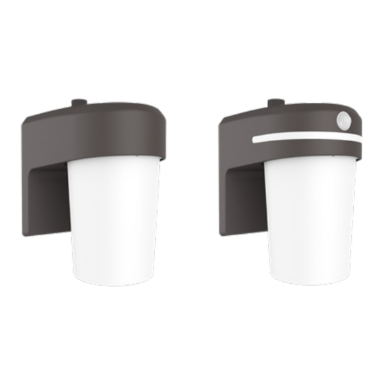
FE08A40FDB
FE12S40FDB
FE10A35GLMB
(Bronze/Bronze/Bronce)
FE08A40FDW
FE12S40FDW
FE10A35GLMW
(White/Blanc/Blanco)
ENGLISH
IITEMS REQUIRED
(Purchase separately)
• Phillips screwdriver
• Weatherproof silicone caulk
IMPORTANT SAFETY INSTRUCTIONS
READ AND FOLLOW ALL SAFETY INSTRUCTIONS AND WARNINGS AND SAVE THESE INSTRUCTIONS:
• Heed all warnings, including below warnings AND those included on product.
• For outdoor use only.
• cULus LISTED for wet location.
• Your fixture is prewired and preassembled for easy installation.
WARNING
• Risk of fire/electric shock. If not qualified, consult an electrician.
• Disconnect power at fuse or circuit breaker before installing or servicing.
CAUTION
• Connect fixture to a 120 volt, 60 Hz power source. Any other connection voids the warranty
• Fixture should be installed by persons with experience in household wiring or by a
qualified electrician. The electrical system, and the method of electrically connecting
the fixture to it, must be in accordance with the National Electrical Code and local
building codes.
• Fixture designed for wall mount to a recessed junction box only. Install fixture to
junction box marked for use in wet locations.
NOTE: This device complies with Part 15 of the FCC Rules. Operation is subject to the
following two conditions: (1) This device may not cause harmful interference, and (2)
this device must accept any interference received, including interference that may cause
undesired operation. Under Part 15 of the FCC Rules, any changes or modifications to
the fixture described in this instruction sheet that are not expressly approved by the
manufacturer could void the user's authority to operate the equipment.
FOR BEST RESULTS
• Install wall sconce 7-10 feet above the ground.
• Do not mount fixture close to reflective surfaces such as windows, white walls, white
surfaces and water.
• When installing two fixtures on one switch, make sure the switch is rated for at least
a 1A inductive load.
Questions?/ Des questions?/ ¿Preguntas? 1-800-334-6871 ConsumerProducts@cooperlighting.com
PACKAGING CONTENTS / CONTENU DE L'EMBALLAGE/ CONTENIDO DEL PAQUETE
A. Light fixture
B. Mounting bracket
Appareil d'éclairage
Support de montage
Accesorio
Soporte de montaje
E. (3) Wire nuts
(3) Capuchons de connexion
(3) Conectores
de cable
Instruction Manual / Manuel d'instructions/ Instrucciones
C. (2) #6 and (2) #8 junction box screws
(use the size that fits your junction box)
(2) Vis nº 6 et 2 vis nº 8 pour boîtier de
jonction (choisissez la dimension convenant
à votre boîtier de jonction)
(2) Tornillos #6 y (2) tornillos #8 para
montaje de la caja de conexión
(utilice el tamaño que mejor se
adecue a su caja de conexión)
MOUNTING YOUR FIXTURE
NOTE: Do not mount within 2 feet of a highly reflective
exterior inside corner (Fig. 1).
1. Turn off the power at the main fuse/breaker box.
2. Attach mounting bracket (B) to junction box with
two screws (C) provided (Fig. 2).
D
4
WIRING YOUR FIXTURE
1. Connect the black fixture wire to the black supply
wire (hot) using wire connector (E) (Fig. 3).
2. Connect the white fixture wire to the white supply
D
wire (neutral) using wire connector (E) (Fig. 3).
3. Connect the copper ground fixture wire to an
appropriate supply ground or a grounded
C
junction box.
NOTE: Be careful to connect the wires correctly.
Make sure no bare strands of wire extend from the
wire connector (E) provided or other approved wire
connectors (not provided).
C
4. Attach fixture to the J-Box by securing it with
screw (D). (Fig. 4)
5. Add silicone caulk around fixture to help maintain a
weather-resistant seal.
B
ADJUSTING THE LUMEN OUTPUT
B
• FE12 series of the product features Lumen
selectable option. Choose between three preset
Lumen outputs ( 700lm ,900lm and 1200lm) during
Fig:5
or after installation. (Fig. 5)
• These Lumen settings can be selected using the
Lumen button provided on the housing.
A
A
USING PHOTOCELL OPTION
4
• Unscrew the Photocell Cap(F) to activate the
photocell sensor (Fig 6)
1
F. Photocell cap
Capuchon de cellule photoélectrique
Tapa de fotocélula
4
D
3
C
Fig:4
B
A
Fig:5
4
3
D.
Screw
Visser
Tornillo
1
2 ft.
4
2 ft.
2 ft.
3
2
Junction box
2
1
C
B
C
3
Junction box
Fig:4
A
E
4
Junction box
Fig:5
A
E
D
5
4
Fig:6
3
6
2
1
3
2
3
2
Publicité

Manuels Connexes pour Cooper Lighting Solutions HALO FE08A40FDB


Sommaire des Matières pour Cooper Lighting Solutions HALO FE08A40FDB
- Page 1 Instruction Manual / Manuel d’instructions/ Instrucciones Questions?/ Des questions?/ ¿Preguntas? 1-800-334-6871 ConsumerProducts@cooperlighting.com PACKAGING CONTENTS / CONTENU DE L’EMBALLAGE/ CONTENIDO DEL PAQUETE A. Light fixture B. Mounting bracket C. (2) #6 and (2) #8 junction box screws Screw (use the size that fits your junction box) Visser Appareil d’éclairage Support de montage...
- Page 2 WARRANTY OF MERCHANTABILITY OR FITNESS FOR ANY PARTICULAR PURPOSE. CONSERVEZ CES INSTRUCTIONS. Cooper Lighting Solutions warrants to customers that, for a period of five years from the date of purchase, Cooper Lighting Solutions products will be free from defects in materials and POUR DES RÉSULTATS OPTIMAUX...
- Page 3 écrit de Cooper Lighting Solutions. Problème Cause Solution a reproduction de ce document est strictement interdite sans l’autorisation préalable par écrit de Cooper Lighting Solutions Pour assistance, appelez le 1-800-334-6871 ou envoyez-nous un courriel à consumerproducts@CooperLighting.com. La lampe ne Aucune tension n'arrive •...
- Page 4 La reproducción de este documento sin la aprobación previa por escrito de Cooper Lighting Solutions está estrictamente prohibida. Para solicitar ayuda, llame al 1-800-334-6871 o envíe un correo electrónico a DIAGNOSTICO Y SOLUCION DE PROBLEMAS ConsumerProducts@CooperLighting.com.