Table des Matières
Publicité
Les langues disponibles
Les langues disponibles
Liens rapides
ioXpander-8 Module
Internal wired 8 I/O expander for PowerMaster-33 control panel
1. Introduction
The ioXpander-8 module enhances the PowerMaster-33 control panel with 8 programmable wired zone inputs or
outputs. The behavior of each wired PGM output can be configured and each wired zone input can be set up with a
location and type.
The ioXpander-8 module is optional, and can be installed in a PowerMaster-33 EXP control panel with version 19.2 or
higher.
2. Installation and wiring
Figure 2.1 – ioXpander-8 Mounting and Wiring
A. Clips
B. Back panel
Figure 2.2 – Location of pinouts
D-306966 IoXpander-8 Module Installation Instructions
C. Expander Module flat cable
D. Connecting devices
Installation Instructions
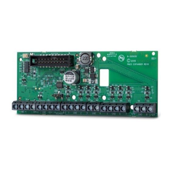
Fig. 1 ioXpander-8 Module
Notes for ioXpander-8 module wiring:
Wired zone terminals can be connected to a normally closed contact of
a detector, switch (for example a tamper switch of any device), or a
Ω
pushbutton, via a 2.2 K
resistor. The 12V terminal can be used to
supply 12V to low power detectors with up to 10mA standby current
drain as DA-5; PL-1; Next_PIR; Vi-Motion; Vi-Pet.
IMPORTANT! The terminals for internal and external sirens are DC
outputs intended for 12v sirens. Connecting a loudspeaker to any of
these outputs will cause a short circuit and will damage the unit.
The Speech Box is a wired remote speaker and microphone device
for indoor use. It provides two-way voice communication between the
user and the central station using the control panel.
Caution! Do not install or remove the ioXpander-8 module when the
control panel is powered by AC power or battery.
For wired zones, the control panel classifies the events according to
the resistance it measures as shown in the table below.
E.O.L or Arming Key Resistance
Range
Zone
~0 kΩ - 1.76 kΩ
Tamper/ Short circuit
∼1.77 kΩ - 2.64 kΩ
Normal
∼2.65 kΩ - 3.52 kΩ
Tamper
∼3.53 kΩ - 5.26 kΩ
Alarm
∼5.26 kΩ - ∞
Tamper
Pin #1 to #8 can be configured either as zone inputs or as PGM
outputs.
To mount the expander module as shown in Figure 2.1,
complete the following steps:
1.
Press downward on the expander module between the two clips
to insert the module into the back panel. See Figure 2.1
ioXpander-8 Mounting and Wiring (A) to identify the clips.
2.
Connect the ioXpander-8 module by the flat cable to the front
panel expander slot "EXPANDER".
Figure 2.3 – Detector connection example
Arming Key
Tamper
Normal
Tamper
Alarm
Tamper
1
Publicité
Table des Matières

Manuels Connexes pour Visonic ioXpander-8


Sommaire des Matières pour Visonic ioXpander-8
- Page 1 The behavior of each wired PGM output can be configured and each wired zone input can be set up with a location and type. The ioXpander-8 module is optional, and can be installed in a PowerMaster-33 EXP control panel with version 19.2 or higher.
- Page 2 Before enrolling and configuring the module: Check that the ioXpander-8 is installed in the PowerMaster-33. For more information, see Section 2. Check that the KP-250 is enrolled to the PowerMaster-33. For more information, see the KP-250 enrollment procedure in the PowerMaster-33 Installer’s Guide.
-
Page 3: Módulo De Expansión Ioxpander
El comportamiento de cada salida programable cableada es configurable y cada entrada de zona cableada se puede configurar con una ubicación y un tipo. El módulo de expansión ioXpander-8 es optativo y se puede instalar en un panel de control PowerMaster-33 EXP, con la versión 19.2 o posterior. - Page 4 Antes de registrar y configurar el módulo: Compruebe que el ioXpander-8 esté instalado en el PowerMaster-33. Para más información, consulte la sección 2. Compruebe que el KP-250 esté registrador para el PowerMaster-33. Para más información, consulte el procedimiento de registro de KP-250, en la Guía del instalador de PowerMaster-33.
-
Page 5: Installation Et Câblage
Chaque sortie PGM câblée peut être configurée et chaque entrée de zone câblée peut être définie avec un emplacement et un type. Le module d'extension ioXpander-8 est optionnel et peut être monté dans un panneau de commande PowerMaster-33 EXP de version 19.2 ou supérieure. -
Page 6: Caractéristiques Techniques
Avant de vous inscrire et de configurer le module: Vérifiez que l'ioXpander-8 est installé dans le PowerMaster-33. Pour obtenir plus de renseignements, lisez la section 2. Vérifiez que le KP-250 est inscrit sur le PowerMaster-33. Pour plus d'informations, consultez la procédure d'inscription KP-250 dans le Guide de l'installateur PowerMaster-33. - Page 7 Istruzioni di installazione 1. Introduzione modulo expander ioXpander-8 migliora la centrale PowerMaster-33 con 8 ingresso e uscita di zona cablata programmabili. Il comportamento di ciascuna uscita PGM cablata può essere configurato e ciascun ingresso di zona cablato può essere configurato con una posizione e un tipo.
- Page 8 Prima di registrare e configurare il modulo: Controllare che ioXpander-8 sia installato nel PowerMaster-33. Per ulteriori informazioni, vedere la Sezione 2. Controllare che il KP-250 sia registrato nel PowerMaster-33. Per ulteriori informazioni, vedere la procedura di registrazione KP-250 nella Guida per l’installatore del PowerMaster-33.