Publicité
Les langues disponibles
Les langues disponibles
Liens rapides
Description
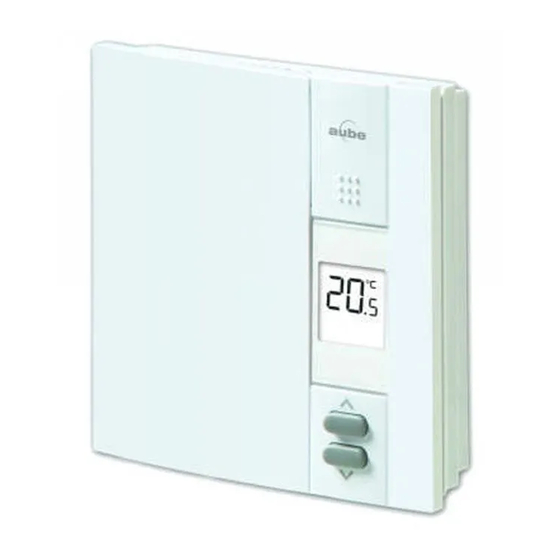
The TH450 thermostat is designed to control an electric heating sys-
tem such as a baseboard heater, a radiant ceiling, a convector or a
fan-forced convector.
Heating intensity
Appears when the thermostat
is configured for a fan-forced
heater.
This thermostat cannot be used with:
•
a resistive load under 1.25 A
•
a resistive load over 16.7 A
•
a system driven by a contactor or a relay (inductive load)
•
a central heating system
SUPPLIED PARTS
•
One (1) thermostat
•
Two (2) 6-32 mounting screws
•
Two (2) solderless connectors
Installation
The installation must be carried out by an electrician and must
comply with local electrical codes.
CUT POWER TO THE HEATING SYSTEM AT THE MAIN
ELECTRICAL PANEL TO AVOID ANY RISK OF ELECTRI-
CAL SHOCK.
Loosen the screw and
remove the faceplate
of the thermostat from
its wallplate.
NOTE:
The
screw
remains captive on the
wallplate.
TH450
Make the connections using solderless connectors for copper wires. The
1.
thermostat wires are non-polarized; this means either wire can be con-
nected to either terminal.
Temperature
display
Keypad lock
WARNING: This thermostat has tinned copper wires for line and load
Temperature
adjustment
connections. Special CO/ALR solderless connectors must be used when
buttons
connecting with aluminium conductors.
Install the wallplate to the electrical box.
Set the configuration switches on the back
of the thermostat's faceplate (see section 3).
2.
Install the faceplate of the thermostat back
on the wallplate and tighten the screw.
NOTE: If there is a protective film or sticker
on the thermostat's screen, peel it off.
Apply power to the thermostat. Verify the installation by checking that the
heater can be turned On and Off by raising and lowering the setpoint
using the
NOTE: Keep the air vents of thermostat clean and unobstructed at all
times.
Non-programmable Thermostat
Electrical
Electrical
panel
box
Thermostat
Electrical
panel
Heater
and
buttons.
TH450
Owner's Guide
Heater
Electrical
box
Thermostat
1/2
Publicité

Sommaire des Matières pour Aube Technologies TH450
- Page 1 The TH450 thermostat is designed to control an electric heating sys- tem such as a baseboard heater, a radiant ceiling, a convector or a Electrical Electrical fan-forced convector.
- Page 2 The screen is backlit for 10 seconds when any button is pressed. J2X 5K8 Canada Power Outage 1-800-831-2823 During a power outage, the setpoint is saved in memory. You do not aube.service@honeywell.com www.aubetech.com need to adjust the temperature when power returns. Printed in USA 06/2011 TH450...
- Page 3 Faire le raccordement en utilisant des connecteurs sans soudure pour fils Description de cuivre. Les fils du thermostat sont non-polarisés; le sens du branche- ment n’a donc aucune importance. Le thermostat TH450 est conçu pour commander un appareil de chauffage électrique tel qu’une plinthe électrique, un plafond radiant, Panneau Boîte électrique...
- Page 4 Panne de courant J2X 5K8 Canada Durant une panne de courant, la température de consigne est sauve- gardée. Vous n’aurez donc pas à régler la température de nouveau 1 800 831-2823 après une panne. aube.service@honeywell.com www.aubetech.com Imprimé aux É.-U. 06/2011 TH450...


