Table des Matières
Publicité
Les langues disponibles
Les langues disponibles
Liens rapides
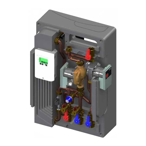
T-FAST ie40
Modulo di produzione ACS
DHW production modules
Frischwasserstationen
Modules de production ECS
Istruzioni per l'installazione, l'uso e la manutenzione
Assembling instructions and maintenance
Montage - und Wartungsanleitung
Instructions relatives à l'installation, l'utilisation et la maintenance
Publicité
Table des Matières

Manuels Connexes pour Lovato T-FAST ie40


Sommaire des Matières pour Lovato T-FAST ie40
- Page 1 T-FAST ie40 Modulo di produzione ACS DHW production modules Frischwasserstationen Modules de production ECS Istruzioni per l’installazione, l’uso e la manutenzione Assembling instructions and maintenance Montage - und Wartungsanleitung Instructions relatives à l’installation, l’utilisation et la maintenance...
- Page 2 SEZIONE 8: TABELLA PARAMETRI REGOLATORE SEZIONE 9: COMPONENTI Illustrazioni e dati presenti si intendono non impegnativi. LOVATO Spa si riserva il diritto di apportare modifiche senza obbligo di preavviso. È vietata la riproduzione parziale o totale di disegni, testi o illustrazioni senza autorizzazione scritta.
- Page 3 La LOVATO S.p.A. non è responsabile del prodotto modificato senza autorizzazione e tanto meno per l’uso di ricambi non originali.
- Page 4 Installazione, uso e manutenzione SEZIONE 2: DATI TECNICI COMPONENTI PRINCIPALI Circolatore primario ad alta efficienza Wilo YONOS PARA 15/1-7 Dima telaio verniciata nera Maniglia nera con termometro rosso (circuito primario) Valvola sfera DN20 M-F 1”- ¾” con valvola di ritegno e calotta Scambiatore di calore a piastre inox saldobrasate con isolamento Valvola di sicurezza 10 bar lato secondario (circuito sanitario) F-F ½”...
- Page 5 Installazione, uso e manutenzione CURVE CARATTERISTICHE CIRCOLATORE CIRCUITO PRIMARIO CIRCOLATORE AD ALTA EFFICIENZA WILO YONOS PARA 15/1-7 Per maggiori informazioni sul circolatore consultare il manuale Wilo all’interno dell’imballo. SCHEMA IDRAULICO 1 Circolatore primario ad alta efficienza 2 Scambiatore a piastre 3 Rubinetto di carico / scarico 4 Valvola sfiato aria 5 Kit ricircolo...
- Page 6 Idrogeno Solforato mg/l <0.05 I materiali di costruzione del modulo di produzione acqua calda sanitaria mod. Ammoniaca mg/l <2 T-FAST ie40 sono conformi a quanto previsto dal D.M. 174/2004, regolamentato Idrogeno Carbonato mg/l <300 dalla Direttiva 98/83/CE. Idrogeno Carbonato/Solforato mg/l >1.0...
- Page 7 Installazione, uso e manutenzione SEZIONE 4: ESEMPIO DI APPLICAZIONE Accumulo tecnico (puffer) Fonte di calore T-FAST ie40 compact Ricircolo Fonte di calore ausiliaria Uscita ACS Rete SEZIONE 5: INSTALLAZIONE CONTROLLI PRELIMINARI Prima di ogni operazione rimuovere con cura l’imballo e controllare la perfetta integrità dell’apparecchiatura. Nel caso si evidenziassero dei difetti o dei danni non installare o cercare di riparare l’apparecchiatura ma rivolgersi al venditore.
- Page 8 Installazione, uso e manutenzione INSTALLAZIONE SU PUFFER ATTENZIONE! MANEGGIARE CON CURA! Estrarre con cura il modulo dall’imballaggio facendo attenzione a non danneggiarlo e rimuovere il coperchio in EPP. ATTENZIONE! L’INTERASSE DEI FORI VA PREVENTIVA- MENTE COMUNICATO AL PRODUTTORE DEL BOILER IN FASE D’ORDINE (SERVIRSI DLLE DISTANZE NELLA FIGURA 4) Allentare le 2 viti della dima di supporto (fig.2) e rimuoverla dalla parte posteriore del modulo.
- Page 9 Installazione, uso e manutenzione INSTALLAZIONE A MURO IMPORTANTE! POSIZIONARE LA STAFFA IN MANIERA CORRETTA Allentare le 2 viti della dima di supporto (fig.2) e rimuoverla dalla parte posteriore del modulo per poi fissarla a parete con n.2 tasselli da 12 mm (non forniti) come indicato nel rif. 2a N.B.
- Page 10 Installazione, uso e manutenzione SEZIONE 6: MESSA IN FUNZIONE 1 - Aprire le valvole a sfera (A e B), riempire il circuito primario e sfiatare l’aria presente attraverso la valvola sfiato (C). 2 - Riempire il circuito secondario (sanitario) utilizzando gli appositi rubinetti di carico/scarico (1 e 2).
- Page 11 Installazione, uso e manutenzione COLLEGAMENTO ELETTRICO KIT RICIRCOLO Lato sonde Pericolo max. 12 V Attenzione Lato linee 230 VAC Linee in tensione 230VAC 50-60Hz Connessione nella parte destra della morsettiera! Bassa tensione max. 12VAC/DC Connessione nella parte destra della morsettiera! Linea principale 230 V Attenzione La polarità...
- Page 12 Installazione, uso e manutenzione SEZIONE 7: COLLEGAMENTO ELETTRICO CABLAGGIO REGOLATORE MFWC COLLEGAMENTO ELETTRICO MODULO CON KIT RICIRCOLO Attenzione Lato sonde Pericolo max. 12 V Lato linee 230 VAC Linee in tensione 230VAC 50-60Hz Connessione nella parte destra della morsettiera! Bassa tensione max. 12VAC/DC Connessione nella parte destra della morsettiera! 22004620...
- Page 13 Installazione, uso e manutenzione SEZIONE 8: TABELLA PARAMETRI REGOLATORE Descrizione menù Descrizione Range impostazioni Default T-FAST ie 40 Impost. Utente 4. IMPOSTAZIONI T set point 30°C ÷ 90°C 45°C T max. 50°C ÷ 95°C 60°C 1÷12 / 1÷20 / 2÷40 / Tipo VFS 2 ÷...
- Page 14 Installazione, uso e manutenzione Descrizione menù Descrizione Range impostazioni Default T-FAST ie 40 Impost. Utente Richiesta / orari / richiesta+orari 6.8.1.2 Ricircolo Orari / sempre acceso Controllo pressione ON / OFF Off / 0÷0,6 bar / 0÷1 bar / 0÷1,6 6.9.2 RPS1/RPS2 bar / 0÷2,5 bar / 0÷4 bar / 0÷6...
- Page 15 Installazione, uso e manutenzione SEZIONE 9: COMPONENTI Misuratore di portata / temperatura VORTEX FLOWSENSOR (VFS) 2 - 40 l/min Vortex Flowsensor è un misuratore combinato di portata / temperatura concepito per la produzione di elevati volumi di acqua. E‘ realizzato in materiale composito, mentre l‘elemento sensibile è a base siliconica realiz- zato con tecnologia MEMS.
- Page 16 Installazione, uso e manutenzione...
- Page 17 SECTION 8: DIGITAL CONTROLLER INITIAL SETTINGS SECTION 9: COMPONENTS Picture and technical data are not binding. LOVATO Spa will reserve the right to bring change without obbligation of notice. It is forbidden reproduce copy, drawing or texties, partial or total without previous written authorization.
- Page 18 DESCRIPTION T-FAST ie40 compact is an instantaneous domestic hot water production module that uses the working principle of a stainless steel plates exchanger. The setting of the domestic hot water outlet temperature (secondary side) happens with the modulation of the primary circuit flow rate through a variable flow pump controlled by MFWC controller (PWM control).
- Page 19 Assembling instrunctions and maintenance SECTION 2: TECHNICAL DATA COMPONENTS High efficiency pump type Wilo YONOS PARA 15/1-7 Black template frame Black handle with red thermometer (primary circuit) Ball valve DN25 with 1”½ nut and check valve Brazed plate iron steel heat exchanger with insulation 10 bar safety valve secondary side (domestic water) F-F ½”...
- Page 20 Assembling instrunctions and maintenance PRIMARY CIRCUIT PUMP CHARACTERISTICS HIGH EFFICIENCY PUMP WILO YONOS PARA 15/1-7 For further informations about the pumps please read the Wilo manuals into the packaging HYDRAULIC CIRCUIT 1 Primary circuit high efficiency pump 2 Plate heat exchanger 3 Sensor pocket 4 Load / drain tap 5 Manual air vent...
- Page 21 Assembling instrunctions and maintenance SECTION 3: DIMENSION AND CONNECTION ¾” F 1”M DHW return Primary supply Fig.1 Primary return DHW outlet Fig.1 M-F 1-¾” DCW inlet ¾” F ¾” F ¾” F 1”M 1”M 1”M LIMIT VALUES FOR COPPER DESCRIPTION UNIT SOLDERED HEAT EXCHANGER 7-9 (including saturation factor)
- Page 22 Assembling instrunctions and maintenance SECTION 4: EXAMPLE OF USE Puffer Energy supplier T-FAST ie40 compact DHW return Energy supplier (optional) DHW outlet inlet SECTION 5: INSTALLATION PRELIMINARY CHECK Before every operation carefully remove the packaging and verify if there is external damages. In case of damages please do not install the products.
- Page 23 Assembling instrunctions and maintenance INSTALLATION ON THE PUFFER ATTENTION! HANDLE IT WITH CARE! 1. Pull out the module from the package and remove the cover. ATTENTION! THE HOLES CENTER DISTANCE HAS TO BE TRANSMITTED TO THE BOILER’S MANUFAC- TURER WHEN PLACING THE ORDER (USE THE DISTANCE IN THE PICTURE 3) Slacken the 2 screws of the support jig (pic.2) and remove it from the back part of the module.
- Page 24 Assembling instrunctions and maintenance INSTALLATION ON THE WALL IMPORTANT! PLACE THE BRACKET IN THE CORRECT PLACE Slacken the 2 screws of the support jig (pic.2) and remove it from the back part of the module. Fix it on the wall with nr. 2 screw anchors (12 mm not supplied) as indicated in the ref.2 SCREW ANCHORS NOT SUPPLIED...
- Page 25 Assembling instrunctions and maintenance SECTION 6: INSTALLATION 1 - Open the ball valves (A e B), Fill the primary circuit and venting the air through the air vent (C). 2 - Fill the secondary circuit (hygenic water) through the load/ unload caps.
- Page 26 Assembling instrunctions and maintenance DHW RETURN ELECTRIC CONNECTION Sensor side Attention max. 12 V Danger Main voltages 230VAC 50-60Hz Connection on the right part of the Low voltage max. 12VAC/DC terminal board! Connection on the left part of the terminal board! Main 230 V Attention The polarity of the sensors is freely selectable.
- Page 27 Assembling instrunctions and maintenance SECTION 7: ELECTRICAL CONNECTION CABLAGGIO REGOLATORE MFWC T-FAST ELECTRIC CONNECTION WITH MFWC DIGITAL CONTROLLER Put into the digital controller Sensor side Danger max. 12 V main side Attention 230 VAC Low voltage max. 12VAC/DC Connection on the left part of the terminal board! Main voltages 230VAC / 50-60Hz Connection on the right part of the...
- Page 28 Assembling instrunctions and maintenance SECTION 8: ELECTRICAL REGULATOR INITIAL SETTINGS Menu description Description Settings range Default T-FAST ie40 User settings 4. SETTINGS Target temperature 30°C ÷ 90°C 45°C Max temperature 60°C 50°C ÷ 95°C 1÷12 / 1÷20 / 2÷40 / VFS type 5÷100 / 10÷200 / 200÷400...
- Page 29 Assembling instrunctions and maintenance Menu description Description Settings range Default T-FAST ie40 User settings Signal V2 6.8.1.1 Circulation ON/OFF Request / periods / 6.8.1.2 Circulation request+periods / contin. Orari operation Pressure monitor ON / OFF Off / 0÷0,6 bar / 0÷1 bar / 6.9.2...
- Page 30 Assembling instrunctions and maintenance SECTION 9: COMPONENTS Temperature/flow rate gauge VORTEX FLOWSENSOR (VFS) 2 - 40 l/min Vortex Flowsensor is a combined flow rate/temperature gauge projected for high volume water production. It is made of composite material, while the sensor is made of a silicone base realised with MEMS technology. The gauge is corrosion resistant.
- Page 31 Assembling instrunctions and maintenance...
-
Page 32: Table Des Matières
SECTION 9: COMPOSANTS Les illustrations et les données indiquées dans ce catalogne n’engagent pas la société. LOVATO SpA qui se réserve le droit d’apporter des modifications sans obligation de préavis. La reproduction partielle ou totale des plans, des textes ou des illustrations est interdite sans autorisation écrite. -
Page 33: Section 1: Introduction Et Informations Générales
La société LOVATO S.p.A. sauf autorisation ne s’assume aucune responsabilité en présence d’un produit modifié et ceci s’applique aussi lors de l’utilisation de pièces de rechange non originales. -
Page 34: Section 2: Donnèes Techniques
Instructions relatives à l’installation, l’utilisation et la maintenance SECTION 2: DONNèES TECHNIqUES COMPOSANTS PRINCIPAUX Circolateur primaire Wilo YONOS PARA 15/1-7 Dima telaio verniciata nera Poigéee noir avec thermomètre rouge (circuit primaire) Valvola sfera DN20 M-F 1”- ¾” avec vanne de non retour et ecrou Echangeur de chaleur à... -
Page 35: Courbes Des Performances Circulateur Primaire
Instructions relatives à l’installation, l’utilisation et la maintenance COURBES DES PERFORMANCES CIRCULATEUR PRIMAIRE POMPE DE CIRCULATION WILO YONOS PARA 15/1-7 CIRCUIT HYDRAULIQUE 1 Circulateur primaire Echangeur de chaleur 3 Gaine de capteur 4 Robinet de remplissage et de vidange 5 Vanne d’évent de l’air 6 Kit de recirculation 7 Vortex flow sensor 8 Vanne à... -
Page 36: Section 3: Dimensions Et Connexions
Les matériaux de construction du module de production eau chaude sanitaire Ammoniac mg/l <2 modèle T-FAST ie40 respectent la réglementation objet de l’arrêté ministériel Hydrogène mg/l <300 174/2004, et ce conformément à la Directive 98/83/CE. -
Page 37: Section4: Exemple D'application
Instructions relatives à l’installation, l’utilisation et la maintenance SECTION4: EXEMPLE D’APPLICATION Ballon tampon énergie thermique T-FAST ie40 compact Recirculation énergie thermique auxiliaire Sortie ECS Réseau SECTION 5: INSTALLATION CONTROLES PRELIMINAIRES Avant toute opération, veuillez enlever délicatement l’emballage et contrôler l’intégrité parfaite de l’appareillage. Dans le cas où vous constateriez des défauts ou des dommages, veuillez-vous adresser au revendeur et surtout veuillez ne pas installer ou tenter de réparer l’appareillage. - Page 38 Instructions relatives à l’installation, l’utilisation et la maintenance INSTALLATION SUR BALLON TAMPON ATTENTION! MANIPULER EN FAISANT ATTENTION! Extraire de l’emballage le module et enlever le couvercle en EPP. ATTENTION! THE HOLES CENTER DISTANCE HAS TO BE TRANSMITTED TO THE BOILER’S MANUFAC- TURER WHEN PLACING THE ORDER (USE THE DISTANCE IN THE PICTURE 3) Desserrer les 2 vis de la tige de prédisposition (fig.) et enle-...
- Page 39 Instructions relatives à l’installation, l’utilisation et la maintenance INSTALLATION MURALE IMPORTANT! POSITIONNER LE SUPPORT DE FACON CORRECTE Desserrer les 2 vis de la tige de prédisposition (fig.) et enlever cette dernière de la partie arrière du module puis, veuillez la fixersur le mur au moyen de 2 chevilles de 12 mm (non fournies) comme indiqué...
-
Page 40: Section 6: Mise En Service
Instructions relatives à l’installation, l’utilisation et la maintenance SECTION 6: MISE EN SERVICE 1 - Ouvrir le robinet à boisseau sphérique (A e B), remplir le circuit primaire en éliminant complètement l’air présent dans le circuit à travers les vannes de purge (C). 2 - Remplir le circuit secondaire (sanitaire) en utilisant les robinets appropriés d’alimentation / de vidange. - Page 41 Instructions relatives à l’installation, l’utilisation et la maintenance BRANCHEMENT éLECTRIQUE KIT DE RICIRCULATION Côté capteur Danger 12 V max Attention Côté secteur 230 VCA Tensions réseau 230VAC 50-60Hz Connection dans le terminal de droite! Basses tension 12VAC/DC max. Connection dans le terminal de gauche! Tension secteur 230 V Attention...
-
Page 42: Section 7: Branchement Électrique Mfwc
Instructions relatives à l’installation, l’utilisation et la maintenance SECTION 7: BRANCHEMENT ÉLECTRIqUE MFWC CABLAGGIO REGOLATORE MFWC Connecter à le régulateur électronique Danger Côté capteur 12 V max Attention Côté secteur 230 VCA Tensions réseau 230VAC 50-60Hz Connection dans le terminal de droite! Basses tension 12VAC/DC max. -
Page 43: Section 8: Tableau Des Paramètres De La Centrale Mfwc
Instructions relatives à l’installation, l’utilisation et la maintenance SECTION 8: TABLEAU DES PARAMèTRES DE LA CENTRALE MFWC Description menu Description Paramètres Défaut T-FAST ie40 Paramètres utilisateur 4. PARAMÈTRES T cons 30°C ÷ 90°C 45°C T max. 50°C ÷ 95°C 60°C 1÷12 / 1÷20 / 2÷40 /... - Page 44 Instructions relatives à l’installation, l’utilisation et la maintenance Description menu Description Paramètres Défaut T-FAST ie40 Paramètres utilisateur Signal V2 6.8.1.1 Circulation marche/arrêt arrêt Demande / temps / Dem.+temps 6.8.1.2 Circulation Temps / Marche continue Controllo pressione ON / OFF Off / 0÷0,6 bar / 0÷1 bar / 0÷1,6 6.9.2...
- Page 45 Instructions relatives à l’installation, l’utilisation et la maintenance SEZIONE 9: COMPOSANTS Indicateur de température / débit VORTEX FLOWSENSOR (VFS) 2 - 40 l / min Vortex Flowsensor est une jauge de débit / température combinée projetée pour la production d’eau à grand volume.
- Page 46 Instructions relatives à l’installation, l’utilisation et la maintenance...
- Page 48 Smart Energy Solutions www.lovatospa.com LOVATO S.p.A. Via Selva, 4/a +39 045 618 2012 mail 37040 Gazzolo d’Arcole info@lovatospa.com lovatospa fax+39 045 618 2017 VERONA - ITALY...