Publicité
Les langues disponibles
Les langues disponibles
WARNING! READ ! BEFORE INSTALLING
• Install and locate this light in accordance with the installation instructions.
• This light is potentially hazardous if not properly installed.
• This light must be installed in conformance with Article 680 of the Na
tional Electric Code and all local code requirements.
• To reduce the risk of electric shock, a Class A ground fault circuit
interrupter (GFCI) shall be installed in the branch circuit by a licensed
electrician, and all devices in the system must be properly grounded.
DO NOT use extension cord sets.
• The total electrical system must be installed, tested, and approved by
a licensed electrician before it is placed in operation.
water level. The junction box shall be located not less than 8" (20,3 cm) above the pool
water level and not less than 4" (10,2 cm) above the pool deck or ground, whichever is
higher. The junction box shall be located minimum 4 feet (121,9 m) from the perimeter
of the pool, unless separated from the pool by a fence, wall or other permanent
barrier. Junction boxes mounted above grade in the walkway around a pool shall be
Warning : Disconnect all power sources to the pool
equipment before installing this light assembly.
1. Verify that your newly purchased SHW143-PC-1RGB light matches your wattage,
voltage and cord length requirements.
Model IFD Face-Flange Type for LINER pools.
Installation instruction
wall and0.030 inches (0,75 mm) for the liner, and can be mounted before
shipping the pool or panel to the site.
At this point, the pool should be empty with no liner.
Cut a 3-3/8" (86 mm) diameter hole in the required position on the pool wall or
panel, then secure the body (5) through the hole with the spacer lock nut (6)
with water according to the maker's instructions making sure to keep the water level
screws will go. Use the screws to secure the other gasket and the face ring to the body
face ring hole to cut out the liner. Place the light on the deck. Run the end of the cable
down into the pool and into the niche opening. Push the cable into the conduit until it
appears at your wiring junction box. Pull the excess cable through the conduit. Make the
necessary connections as explained on page 2. Finish the installation by screwing the
light in place using the installation tool (7). Add a ¼ turn after you have felt resistance .
M10064C
LIGHT INSTALLATION
INSTALLATION
GUIDE
lOCK NUT
POOL
6
WALL
5
STARLIGHT
9413-2012-(0050,0100,0150)
FIG. A
POOL WALL
SPACER
BODY
FIG. B
LINER
4
3
4
2
FIG. C
No.
Description
1
Light (50ft cord)
1
Light (100ft cord)
1
Light (150ft cord)
2
O-Ring
3
Face Flange
4
Gasket
5
Body
6
Spacer Lock Nut
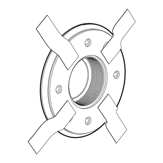
Installation tool
7
LINER
FACE FLANGE
LED
LIGHT
O-RING
SCREW
GASKETS
1
7
Qty
Part Number
1
9413-2012-0050
1
9413-2012-0100
1
9413-2012-0150
1
47-0218-03R
1
43-0619-02R
2
13-0870-02R
1
88-3153-00R
1
31-0418-20R
1
23-4980-40
1
Publicité
Table des Matières

Sommaire des Matières pour CARVIN 9413-2012-0050
- Page 1 Use the screws to secure the other gasket and the face ring to the body Description Part Number Light (50ft cord) 9413-2012-0050 face ring hole to cut out the liner. Place the light on the deck. Run the end of the cable Light (100ft cord) 9413-2012-0100 down into the pool and into the niche opening.
-
Page 2: Brief Introduction
CONTROL STARTER KIT USER GUIDE STARLIGHT 9413-2660 Brief introduction STARLIGHT is a LED lighting system for inground pools, designed to be installed inside water return outlets. The starter kit includes a remote control, a six outlet controller, an AC adapter and the installation tool. You can connect up to six STARLIGHT lights (individually sold separately) to the controller to work in a synchronized way. - Page 3 No. de pièce tranchant pour découper la doublure à l’intérieur de la bride frontal. Déposer l’Appareil Lumière (câble 50pi. ) 9413-2012-0050 d’éclairage sur la terrasse et faites descendre l’extrémité du cordon dans la piscine jusque Lumière (câble 100pi. ) 9413-2012-0100 dans l’ouverture de la niche.
-
Page 4: Ensemble Contrôleur
ENSEMBLE CONTRÔLEUR GUIDE D’UTILISATION STARLIGHT 9413-2660 Brève introduction STARLIGHT est un système de lumières au DEL pour piscines creusées qui s’installent dans les raccords de retour d’eau. L’ensemble CONTRÔLEUR STARLIGHT comprend une télécommande, un contrôleur à six prises, un adaptateur CA et un outil d’installation. Une possibilité... - Page 5 No de Pieza Empuje el cable por el conducto hasta que salga a la caja eléctrica. Hale el LUZ (50 pies de cable) 9413-2012-0050 exceso de cable. Haga las conexiones necesarias según la pagina 2. Finaliza LUZ (100 pies de cable) 9413-2012-0100 la instalación enroscando la luz usando la herramienta de instalación (7).
-
Page 6: Control Remoto
KIT DE CONTROL DE ENCENDIDO GUÍA DEL STARLIGHT 9413-2660 USUARIO introducción STARLIGHT es un sistema de luz LED para piscinas de concreto, diseñado para estar instalado dentro de los retornos. El kit de encendido incluye un control remoto, un control de 7 puntos de conexión, un adaptador de AC y una herramienta de instalación. Puede conectar hasta 6 STARLIGHTS (vendidas por separado cada una) al control para que trabajen sincronizadamente.