Table des Matières
Publicité
Liens rapides
www.sollatek.com
th e po wer to pr o t ect
t h e p o w er t o pr o t e c t
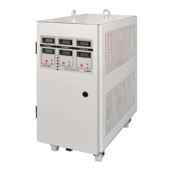
The Sollatek three phase
Automatic voltage regulator (AVR)
www.s ol la tek . c om
Régulateur de tension automatique triphasé (RTA)
Instruction Manual
Issue: January 2016
Édition : Janvier 2016
Important: This manual contains important safety instructions.
Keep this manual handy for reference.
Notice importante : ce manuel renferme des instructions de sécurité importantes.
Garder cette publication en lieu accessible afin d'en faciliter la consultation rapide
Publicité
Table des Matières

Manuels Connexes pour Sollatek AVR3x20-22

Sommaire des Matières pour Sollatek AVR3x20-22
- Page 1 The Sollatek three phase Automatic voltage regulator (AVR) www.s ol la tek . c om Régulateur de tension automatique triphasé...
-
Page 2: Table Des Matières
Page 2 THREE PHASE AUTOMATIC VOLTAGE REGULATOR Issue: Jan 2016 ENGLISH FRANÇAIS Table of contents Table des matières SECTION PAGE SECTION PAGE 1. Déballage et Inspection 1. Unpacking and Inspection 2. Installation * 2. Installation 2.1 Safety 2.1 Sécurité 2.2 Situation 2.2 Positioning 2.3 Ventilation 2.3 Ventilation... -
Page 3: Unpacking And Inspection
THREE PHASE AUTOMATIC VOLTAGE REGULATOR Issue: Jan 2016 Page 3 1. Unpacking and Inspection It is possible that the unit will have sustained damage during transit. The following procedure should be followed immediately upon receipt of the unit. Crate/Packaging - Check for transit damage. Cabinet/Casework - Check for visible signs of damage to exterior panels, doors and fittings. -
Page 4: Circuit Breakers
Ventilation - The unit should be positioned such that a free flow of air is available. It is especially Sollatek UK Ltd. http://www.sollatek.com important to ensure that cooling fan outlets are free from obstruction. A free space of at least 300mm should be... - Page 5 N = Fully rated neutral in INPUT C.B. E = Supply earth OUTPUT SIDE R1 = Phase 1 out Sollatek UK Ltd. http://www.sollatek.com S2 = Phase 2 out T3 = Phase 3 out Diagram 2.6.1 Typical Terminal Arrangement N = Fully rated neutral out...
-
Page 6: System Power-Up
Page 6 THREE PHASE AUTOMATIC VOLTAGE REGULATOR Issue: Jan 2016 3. System power-up (Standard Version) Before the system is powered-up for the first time the following checks should be carried out by qualified personnel only. Inspect the input and output terminations for tightness, correct wiring and phase rotation. Check that the building electrical service is of sufficient capacity to supply the input current of the AVR, remembering that this can be 40% higher than the output current to the load. -
Page 7: Avs Function
THREE PHASE AUTOMATIC VOLTAGE REGULATOR Issue: Jan 2016 Page 7 Triac banks to cope with motor start loads. Low value resistors are fitted with each Triac to ensure that high currents are shared equally between the Triacs within each bank. This technique results in a voltage stabiliser which has no moving parts, responds quickly to voltage fluctuations and is not as large or heavy as other AVRs utilising different regulation techniques. -
Page 8: Principle Of Operation
Page 8 THREE PHASE AUTOMATIC VOLTAGE REGULATOR Issue: Jan 2016 The parameters monitored by the Three Phase AVS are: Value of the Mains Voltage The normal condition is when the values of the mains voltage of all the phases are within certain preset limits referred to as the "window". -
Page 9: Bypass Option
Again ensure the power is turned off before starting work. If the AVR is damaged for any reason, or you suspect a fault, contact your nearest Sollatek agent or Sollatek (UK) Ltd Head office for advice. -
Page 10: Trouble Shooting
Page 10 THREE PHASE AUTOMATIC VOLTAGE REGULATOR Issue: Jan 2016 6 Trouble Shooting 6.1 Safety - Under no circumstances should any work be carried out on the unit unless the supply is isolated. 6.2.False Starting. If it is found that the AVR keeps trying to start but turns off immediately, this is most likely to be due to poor wiring to the AVR or in the building. -
Page 11: Error Modes
The square LEDs in a group scan in a cyclical pattern starting at the top moving to the bottom repeatedly. This indicates that a fault has occurred in the voltage measurement feedback circuit. Contact your nearest Sollatek agent or Sollatek (UK) for advice. - Page 12 Page 12 THREE PHASE AUTOMATIC VOLTAGE REGULATOR Issue: Jan 2016 Model Weight Dims (mm) W x D x H AVR3x20-22 450 x 635 x 850 AVR3x30-22 450 x 635 x 850 AVR3x50-22 500 x 685 x 1060 AVR3x75-22 600 x 735 x 1110...
- Page 13 In this case, the bypass is used to select between the regulated supply from the AVR and the incoming mains supply as the feed to the load. Connections SOLLATEK U. K . LTD. are as indicated on the terminal panel with the exception the terminals marked ‘TO AVR’...
- Page 14 Page 14 THREE PHASE AUTOMATIC VOLTAGE REGULATOR Issue: Jan 2016 Page: 2 1...
- Page 15 THREE PHASE AUTOMATIC VOLTAGE REGULATOR Issue: Jan 2016 Page 15 APPENDIX 2 System topology diagrams 1. Main AVR 2. Main power PCBs 3. Cooling fans 4. LCD Display 5. Distribution surge protection 6. Fuse PCB 7. Automatic Voltage Switcher...
- Page 16 Page 16 THREE PHASE AUTOMATIC VOLTAGE REGULATOR Issue: Jan 2016 Page: 2 4...
- Page 17 THREE PHASE AUTOMATIC VOLTAGE REGUL ATOR Issue: Feb 2002 THREE PHASE AUTOMATIC VOLTAGE REGULATOR Issue: Jan 2016 Page 17 Page: 2 5...
- Page 18 Page 18 THREE PHASE AUTOMATIC VOLTAGE REGULATOR Issue: Jan 2016 THREE PHASE AUTOMATIC VOLTAGE REGUL ATOR Issue: Feb 2002 RevNo Revision note Date Size Quantity Material- Article No./Reference Finish- 1216 Designed by Checked by Approved by - date Date Scale 185001 14/3/01 Title:...
- Page 19 THREE PHASE AUTOMATIC VOLTAGE REGULATOR Issue: Jan 2016 Page 19 THREE PHASE AUTOMATIC VOLTAGE REGUL ATOR Issue: Feb 2002 Page: 2 7...
- Page 20 THREE PHASE AUTOMATIC VOLTAGE REGUL ATOR Issue: Feb 2002 Page 20 THREE PHASE AUTOMATIC VOLTAGE REGULATOR Issue: Jan 2016 Page: 2 8...
- Page 21 THREE PHASE AUTOMATIC VOLTAGE REGULATOR Issue: Jan 2016 Page 21 THREE PHASE AUTOMATIC VOLTAGE REGUL ATOR Issue: Feb 2002 RevNo Revision note Date Size Quantity Material- Article No./Reference Finish- 1213 Designed by Checked by Approved by - date Filename Date Scale 184701 13/3/01...
- Page 22 Page 22 THREE PHASE AUTOMATIC VOLTAGE REGULATOR Issue: Jan 2016 THREE PHASE AUTOMATIC VOLTAGE REGUL ATOR Issue: Feb 2002 Page: 3 0...
-
Page 23: Inspection Checklist
THREE PHASE AUTOMATIC VOLTAGE REGULATOR Issue: Jan 2016 Page 23 Final Test Procedure Document Number: QP07 Product Name: Installed Large AVR Variants: All ST165 based Inspection Checklist 1. Check PCBs for damage, poor alignment, comb positioning and general condition. 2. Ensure that all internal nuts, bolts and fixings are secure and that nothing has come loose during installation. 3. - Page 24 Page 24 THREE PHASE AUTOMATIC VOLTAGE REGULATOR Issue: Jan 2016 Inspection and Test Document Number: QF07 Product Name: Installed Large AVR Variants: All ST165 based Inspection Checklist 1. PCBs 2. Assembly 3. Wiring 4. Exterior Function Test Tick for pass and enter value R1 (value) S2 (value) T3 (value)
- Page 25 THREE PHASE AUTOMATIC VOLTAGE REGULATOR Issue: Jan 2016 Page 25 AVR on-site repair guide Power PCB replacement procedure (Single PCB per Stack) Ensure the AVR is isolated from the supply and load before commencing 1. Remove neutral sense cable (Single cable connected to J5) 2.
- Page 26 Page 26 THREE PHASE AUTOMATIC VOLTAGE REGULATOR Issue: Jan 2016 In the large AVRs the main circuit boards are type ST165. There is one master PCB per phase and several slaves. In the picture below of an AVR3x400, there is one master and 7 slave PCBs. Pink/Grey fuse (in 7 Slave PCBs (ST165) Brass pillars...
- Page 27 THREE PHASE AUTOMATIC VOLTAGE REGULATOR Issue: Jan 2016 Page 27 5. DSP replacement procedure Ensure the AVR is isolated from the supply and load before commencing 1. Remove AVR back panel by undoing securing screws. 2. Remove cable access cover by undoing securing screws. The screws are covered by plastic inserts which must be removed.
- Page 28 Page 28 THREE PHASE AUTOMATIC VOLTAGE REGULATOR Issue: Jan 2016 AVS Contactor replacement procedure Ensure the AVR is isolated from the supply and load before commencing 1. Remove AVR back panel by undoing securing screws. 2. Note all wiring positions. 3.
- Page 29 THREE PHASE AUTOMATIC VOLTAGE REGULATOR Issue: Jan 2016 Page 29 On Site AVR Test procedures following maintenance/repair Items Required: Single Phase Variac (Variable Transformer) Multimeters Clamp-on Current Meter Test lamp ‘Safebloc’ Safety Mains Connector Following Master PCB Replacement The AVR should be disconnected from Mains and Load before commencing this test. 1.
- Page 30 Page 30 THREE PHASE AUTOMATIC VOLTAGE REGULATOR Issue: Jan 2016 check that the voltage rises and drops in the same way a further 5 times. The round LEDs should move step at a time to the end. Check P1 points to 230V on the PCB ident, +/-5V. 19.
- Page 31 THREE PHASE AUTOMATIC VOLTAGE REGULATOR Issue: Jan 2016 Page 31 3. Connect Multimeter #2 to AVR output 4. Increase input volts to 170V. 5. Digital meter should indicate 170V when set to Input Volts using push-button. 6. Digital meter should indicate 234V when set to Output Volts using push-button. 7.
- Page 32 Page 32 THREE PHASE AUTOMATIC VOLTAGE REGULATOR Issue: Jan 2016...
- Page 33 THREE PHASE AUTOMATIC VOLTAGE REGULATOR Issue: Jan 2016 Page 33...
- Page 34 Page 34 THREE PHASE AUTOMATIC VOLTAGE REGULATOR Issue: Jan 2016...
- Page 35 THREE PHASE AUTOMATIC VOLTAGE REGULATOR Issue: Jan 2016 Page 35...
- Page 36 Page 36 THREE PHASE AUTOMATIC VOLTAGE REGULATOR Issue: Jan 2016...
- Page 37 THREE PHASE AUTOMATIC VOLTAGE REGULATOR Issue: Jan 2016 Page 37...
- Page 38 Page 38 THREE PHASE AUTOMATIC VOLTAGE REGULATOR Issue: Jan 2016...
- Page 39 THREE PHASE AUTOMATIC VOLTAGE REGULATOR Issue: Jan 2016 Page 39...
- Page 40 C20-26 - 2 & 3 WAY = 4.7UF REV: DATE: 14.03.2000 ENG: C20-26 - 4 & 5 WAY = 10UF PROJECT: ST1654D AVR TRIAC DRIVE CIRCUIT COMPANY: SOLLATEK (UK) LIMITED ADDRESS: 4 TRIDENT INDUSTRIAL ESTATE CITY BLACKTHORNE ROAD, POYLE, SLOUGH COUNTRY: UNITED KINGDOM SL3 0AX INITIAL 01.04.1999...
- Page 41 THREE PHASE AUTOMATIC VOLTAGE REGULATOR Issue: Jan 2016 Page 41...
-
Page 42: Déballage Et Inspection
Page 42 RÉGULATEUR DE TENSION AUTOMATIQUE TRIPHASÉ Édition : Jan 2016 TABLE DES MATIÈRES SECTION PAGE Déballage et Inspection Installation * Sécurité Situation Ventilation Câbles et bornes Rupteurs Raccordements d’entrée Raccordements de sortie Mise sous tension du système Descriptif fonctionnel Fonctionnement général Fonctionnement du RTA Fonctionnement du STA... - Page 43 Page 43 RÉGULATEUR DE TENSION AUTOMATIQUE TRIPHASÉ Édition : Jan 2016 Déballage et Inspection Il est possible que le matériel ait subi une avarie en cours de livraison. Adopter la procédure qui suit dès réception de l’unité. Caisse/Emballage – vérifier contre toute avarie survenue en cours de livraison. Armoire/Bâti - Vérifier contre tout signe d’endommagement des panneaux extérieurs, des portes et des accessoires.
- Page 44 Laisser un espace dégagé minimum de 300 mm dans toutes les directions autour du RTA. Câbles et terminaisons – avant d’effectuer un raccordement quelconque les dimensions de câbles entrants et sortants doivent être Sollatek UK Ltd. http://www.sollatek.com...
- Page 45 R1 = Entrée Phase 1 ENTRÉE S2 = Entrée Phase 2 T3 = Entrée Phase 3 N = Entrée neutre puissance nominale Sollatek UK Ltd. E = Terre alimentation http://www.sollatek.com Schéma 2.6.1 Disposition typique des bornes ALIMENTATION SECTEUR DE SORTIE...
-
Page 46: Mise Sous Tension Du Système
Page 46 RÉGULATEUR DE TENSION AUTOMATIQUE TRIPHASÉ Édition : Jan 2016 Mise sous tension du système (Version Série) Avant la première mise sous tension du système les contrôles suivants doivent être effectués, exclusivement par un personnel qualifié. Contrôler le resserrage, le bon câblage et la rotation des phases au niveau des bornes d’entrée et de sortie. Vérifier que les capacités d’alimentation en courant électrique du bâtiment correspondent adéquatement aux besoins en courant d’alimentation d’entrée dans le RTA, sans oublier que ce couranti peut dépasser de 40% le courant de sortie vers la charge. -
Page 47: Fonctionnement Du Sta
Page 47 RÉGULATEUR DE TENSION AUTOMATIQUE TRIPHASÉ Édition : Jan 2016 rangées de thyristors triodes généreusement dimensionnés pour tolérer les charges de démarrage des moteurs. Des résistances de faible valeur sont intégrées dans chaque rangée de thyristors triodes pour garantir que les courants élevés seront répartis entre les thyristors dans chaque rangée. -
Page 48: Principe Du Fonctionnement
Page 48 RÉGULATEUR DE TENSION AUTOMATIQUE TRIPHASÉ Édition : Jan 2016 Les paramètres contrôlés par le STA triphasé sont : Valeur de la tension du secteur En condition normale, les valeurs de la tension secteur de toutes les phases retombent dans certaines limites présélectionnées (appelées ici la «... -
Page 49: Protecteur De Surtension
De nouveau, s’assurer que le courant a été débranché avant toute intervention. Si le RTA subit une avarie quelconque ou si vous pensez qu’un défaut affecte le matériel, contacter votre représentant Sollatek le plus proche ou bien adressez-vous au siège britannique de Sollatek (UK) Ltd pour obtenir des conseils appropriés. -
Page 50: Diagnostic
Page 50 RÉGULATEUR DE TENSION AUTOMATIQUE TRIPHASÉ Édition : Jan 2016 Diagnostic Sécurité – ne jamais intervenir dans l’unité sans avoir isolé le courant. Faux démarrages Si le RTA tente à plisueurs reprises de se mettre en marche mais avec une coupure immédiate, cela résulte vraisemblablement d’un mauvais câblage vers le RTA ou bien dans le bâtiment généralement. -
Page 51: Modes D'erreur
Ce balayage de haut en bas indique qu’une erreur s’est produite dans le circuit témoin de mesure de tension. Solliciter les conseils de votre représentant Sollatek le plus proche, ou contacter Sollatek Royaume-Uni en direct. - Page 52 Page 52 RÉGULATEUR DE TENSION AUTOMATIQUE TRIPHASÉ Édition : Jan 2016 Modèle Poids Dims (mm) W x D x H AVR3x20-22 450 x 635 x 850 AVR3x30-22 450 x 635 x 850 AVR3x50-22 500 x 685 x 1060 AVR3x75-22 600 x 735 x 1110...
-
Page 53: Annexe
RTA est contourné. TERRE Raccordement alternatif de la dérivation SOLLATEK U. K . LTD. Il existe une éthode alternative facultative pour faire le raccordement dérivation/ Figure 2 Repérage de la RTA. Dans ce cas la dérivation sert à choisir comme source de la charge entre plaque à... - Page 54 Page 54 RÉGULATEUR DE TENSION AUTOMATIQUE TRIPHASÉ Édition : Jan 2016 Page: 2 1...
- Page 55 Page 55 RÉGULATEUR DE TENSION AUTOMATIQUE TRIPHASÉ Édition : Jan 2016 ANNEXE 2 Schémas topologiques des circuits RTA principal Plaquettes imprimées courant principal Ventilateurs de refroidissement Affichagepar cristaux liquides Protection contre les surtensions Plaquette imprimée fusibles Sélecteur de tension automatique (STA)
- Page 56 Page 56 RÉGULATEUR DE TENSION AUTOMATIQUE TRIPHASÉ Édition : Jan 2016 Page: 2 4...
- Page 57 THREE PHASE AUTOMATIC VOLTAGE REGUL ATOR Issue: Feb 2002 Page 57 RÉGULATEUR DE TENSION AUTOMATIQUE TRIPHASÉ Édition : Jan 2016 Page: 2 5...
- Page 58 Page 58 RÉGULATEUR DE TENSION AUTOMATIQUE TRIPHASÉ Édition : Jan 2016 THREE PHASE AUTOMATIC VOLTAGE REGUL ATOR Issue: Feb 2002 RevNo Revision note Date Size Quantity Material- Article No./Reference Finish- 1216 Designed by Checked by Approved by - date Date Scale 185001 14/3/01...
- Page 59 Page 59 RÉGULATEUR DE TENSION AUTOMATIQUE TRIPHASÉ Édition : Jan 2016 THREE PHASE AUTOMATIC VOLTAGE REGUL ATOR Issue: Feb 2002 Page: 2 7...
- Page 60 THREE PHASE AUTOMATIC VOLTAGE REGUL ATOR Issue: Feb 2002 Page 60 RÉGULATEUR DE TENSION AUTOMATIQUE TRIPHASÉ Édition : Jan 2016 Page: 2 8...
- Page 61 Page 61 RÉGULATEUR DE TENSION AUTOMATIQUE TRIPHASÉ Édition : Jan 2016 THREE PHASE AUTOMATIC VOLTAGE REGUL ATOR Issue: Feb 2002 RevNo Revision note Date Size Quantity Material- Article No./Reference Finish- 1213 Designed by Checked by Approved by - date Filename Date Scale 184701...
- Page 62 Page 62 RÉGULATEUR DE TENSION AUTOMATIQUE TRIPHASÉ Édition : Jan 2016 THREE PHASE AUTOMATIC VOLTAGE REGUL ATOR Issue: Feb 2002 Page: 3 0...
-
Page 63: Procédure D'essai Finale
Page 63 RÉGULATEUR DE TENSION AUTOMATIQUE TRIPHASÉ Édition : Jan 2016 Procédure d’essai finale Document no. QP07 Nom du produit : RTA installé, grand format Variantes : toutes fondées sur ST165 Liste de vérifications Vérifier les plaquettes imprimées contre tout signe d’avarie, les mauvais alignements, la position des broches, l’état général. -
Page 64: Inspection Et Essais
Page 64 RÉGULATEUR DE TENSION AUTOMATIQUE TRIPHASÉ Édition : Jan 2016 Inspection et essais Document no. QF07 Nom du produit : RTA installé, grand format Variantes : toutes fondées sur ST165 Liste de vérifications Plaquettes à circuits imprimés Montage Câblage Extérieur Test fonctionnel Mettre une croix dans les cases des tests acceptables ;... -
Page 65: Guide Pour La Réparation Du Rta À Pied D'oeuvre
Page 65 RÉGULATEUR DE TENSION AUTOMATIQUE TRIPHASÉ Édition : Jan 2016 Guide pour la réparation du RTA à pied d’oeuvre Procédure de remplacement de la plaquette à circuits imprimés courant (1 seule plaquette par pile) S’assurer que le RTA est isolé de l’alimentation et de la charge avant de commencer toute intervention. Ôter le câble de détection du neutre (câblesimple, relié... - Page 66 Page 66 RÉGULATEUR DE TENSION AUTOMATIQUE TRIPHASÉ Édition : Jan 2016 Dans les RTA de grand format les principales plaquettes à circuits imprimés sont du type ST165. Il y a une plaquette maître par phase et plusieurs esclaves. Dans l’illustration ci-dessous d’un RTA type AVR3x400 l’on voit une plaquette maître et 7 esclaves Fusible rose/gris (en ligne sur les 7 plaquettes à...
- Page 67 Page 67 RÉGULATEUR DE TENSION AUTOMATIQUE TRIPHASÉ Édition : Jan 2016 Procédure pour remplacement du protecteur de surtension DSP S’assurer que le RTA est isolé de l’alimentation et de la charge avant de commencer. Déposer le panneau arrière du RTA en desserrant ses vis de fixation. Retirer le couvercle donnant accès au câblage en desserrant les vis.
- Page 68 Page 68 RÉGULATEUR DE TENSION AUTOMATIQUE TRIPHASÉ Édition : Jan 2016 Tester selon les instructions de la Procédure de contrôle à pied d’œuvre du RTA. Remettre en place le panneau arrière. Procédure pour le remplacement du contacteur du STA S’assurer que le RTA est isolé de l’alimentation et de la charge avant de commencer Retirer le panneau arrière du RTA en desserrant les vis de fixation.
-
Page 69: Procédure De Contrôle À Pied D'œuvre Suivant Entretien Ou Réparations
Page 69 RÉGULATEUR DE TENSION AUTOMATIQUE TRIPHASÉ Édition : Jan 2016 Procédure de contrôle à pied d’œuvre suivant entretien ou réparations Matériel requis : Transformateur variable monophasé Multimètres Ampèremètre à bride de serrage Voyant d’essai Connecteur de sécurité sur secteur type ‘Safebloc’ Suivant le remplacement de la plaquette à... -
Page 70: Contrôle Fonctionnel Du Lecteur Numérique
Page 70 RÉGULATEUR DE TENSION AUTOMATIQUE TRIPHASÉ Édition : Jan 2016 Réduire lentement le transfo variable et vérifier que la tension de sortie baisse à 220V avant de remonter. Ceci doit se reproduire au total 6 fois. Augmenter puis rabaisser le transfo variable plusieurs fois et s’assurer que toutes les diodes électroluminescentes (LD1 à... - Page 71 Page 71 RÉGULATEUR DE TENSION AUTOMATIQUE TRIPHASÉ Édition : Jan 2016 Le lecteur numérique doit indiquer 234V lorsque réglé sur Volts Sortie par voie du bouton-poussoir. Répéter pour les autres phases. Le contrôle de l’affichage du courant de sortie ne peut s’effectuer que lorsque le RTA est connecté en ligne et sous charge.
- Page 72 Page 72 RÉGULATEUR DE TENSION AUTOMATIQUE TRIPHASÉ Édition : Jan 2016...
- Page 73 Page 73 RÉGULATEUR DE TENSION AUTOMATIQUE TRIPHASÉ Édition : Jan 2016...
- Page 74 Page 74 RÉGULATEUR DE TENSION AUTOMATIQUE TRIPHASÉ Édition : Jan 2016...
- Page 75 Page75 RÉGULATEUR DE TENSION AUTOMATIQUE TRIPHASÉ Édition : Jan 2016...
- Page 76 Page 76 RÉGULATEUR DE TENSION AUTOMATIQUE TRIPHASÉ Édition : Jan 2016...
- Page 77 Page 77 RÉGULATEUR DE TENSION AUTOMATIQUE TRIPHASÉ Édition : Jan 2016...
- Page 78 Page 3878 RÉGULATEUR DE TENSION AUTOMATIQUE TRIPHASÉ Édition : Jan 2016...
- Page 79 Page 79 RÉGULATEUR DE TENSION AUTOMATIQUE TRIPHASÉ Édition : Jan 2016...
- Page 80 C20-26 - 2 & 3 WAY = 4.7UF REV: DATE: 14.03.2000 ENG: C20-26 - 4 & 5 WAY = 10UF PROJECT: ST1654D AVR TRIAC DRIVE CIRCUIT COMPANY: SOLLATEK (UK) LIMITED ADDRESS: 4 TRIDENT INDUSTRIAL ESTATE CITY BLACKTHORNE ROAD, POYLE, SLOUGH COUNTRY: UNITED KINGDOM SL3 0AX INITIAL 01.04.1999...
- Page 81 Page 81 RÉGULATEUR DE TENSION AUTOMATIQUE TRIPHASÉ Édition : Jan 2016...
- Page 82 Page 82 RÉGULATEUR DE TENSION AUTOMATIQUE TRIPHASÉ Édition : Jan 2016...
- Page 83 Page 83 RÉGULATEUR DE TENSION AUTOMATIQUE TRIPHASÉ Édition : Jan 2016...
- Page 84 ©Sollatek (UK) Limited 2012. All Rights Reserved. SOLLATEK Sollatek (UK) Ltd. Sollatek House, Waterside Drive, Langley, Slough SL3 6EZ UK and the SOLLATEK device are the trade marks of the Sollatek group of companies. w w w. s o l l a t ek.c o m...