Table des Matières
Publicité
Les langues disponibles
Les langues disponibles
Liens rapides
Installation & Operating Instructions
EN
MULTI-PURPOSE WATER FILTER
Instructions d'Installation & Emploi
FR
FILTRE D'EAU MULTI-USAGE
Installation- & Gebrauchsanleitung
DE
MEHRZWECK WASSERFILTER
Installatie & Gebruiksinstructies
NL
MULTIFUNCTIONELE WATERFILTER
Instrukcja Instalacji i Eksploatacji
PL
MULTIFUNKCYJNY FILTR WODY
© 2017 erie water treatment
OM-Multimix-Rev2017.01
Publicité
Chapitres
Table des Matières

Sommaire des Matières pour MultiMix Simplex Eco 35690
- Page 1 Installation & Operating Instructions MULTI-PURPOSE WATER FILTER Instructions d’Installation & Emploi FILTRE D’EAU MULTI-USAGE Installation- & Gebrauchsanleitung MEHRZWECK WASSERFILTER Installatie & Gebruiksinstructies MULTIFUNCTIONELE WATERFILTER Instrukcja Instalacji i Eksploatacji MULTIFUNKCYJNY FILTR WODY © 2017 erie water treatment OM-Multimix-Rev2017.01...
- Page 2 EN English........................Page 3 FR Français ........................Page 15 DE Deutsch ........................Seite 27 NL Nederlands ......................... Pagina 39 PL Polski.......................... Strona 51...
-
Page 3: Table Des Matières
TABLE OF CONTENT & INSTALLATION RECORD Table of content & Installation record ..................Page 3 Warning & Safety instructions ....................Page 4 Operating conditions & Requirements .................Page 5 Assembly..........................Page 6 Installation ...........................Page 7 Start-up ..........................Page 8 Electronic control panel .......................Page 9 Maintenance ........................Page 11 Composition overview ......................Page 12 For future reference, fill in the following data INSTALLATION RECORD... -
Page 4: Warning & Safety Instructions
WARNING & SAFETY INSTRUCTIONS Before you begin the installation of the multi-purpose water filter, we advise you read and carefully follow the instructions contained in this manual. It contains important information about safety, installation, use and maintenance of the product. The actual system that you have received, may differ from the pictures/illustrations/descriptions in these Instructions. -
Page 5: Operating Conditions & Requirements
OPERATING CONDITIONS & REQUIREMENTS APPLICATION LIMITATIONS: pH: 5-10 maximum contaminant content: Water hardness 75 °f / 42 °d Iron (Fe 15 mg/L Manganese (Mn 3 mg/L Oxidizability (O 4 mg/L Ammonia (NH 4 mg/L OPERATING PRESSURE: MIN-MAX: 1,4-8,3 bar / 20-120 psi ... -
Page 6: Assembly
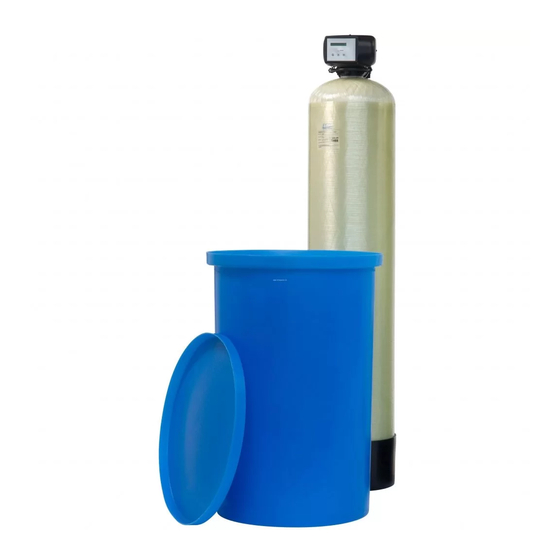
ASSEMBLY CONTENT CHECK BRINE TANK Actual parts that you have received, may differ from the Picture 1 pictures/illustrations in these Instructions! 11. Move the brine tank to the correct installation location; position it on a flat and level surface. Make sure to leave For ease of transportation and installation, the filter enough space for ease of service. -
Page 7: Installation
INSTALLATION INLET & OUTLET DRAIN Check the water pressure at the place of installation of We recommend the use of a stand pipe with air trap. the multi-purpose water filter; it should never exceed 8,3 To prevent backflow from the sewerage system into the bar. -
Page 8: Start-Up
START-UP PRESSURIZING 1. Put the bypass system in 'bypass' position. 2. Make sure the electronic controller of the multi-purpose water filter is in service mode. 3. Open the mains water supply. 4. Open a cold treated water faucet nearby the multi- purpose water filter and let the water run for a few minutes until all air is purged and all foreign material that may have resulted from the installation is washed out;... -
Page 9: Electronic Control Panel
ELECTRONIC CONTROL PANEL Picture 6 SERVICE MODE In service mode the display shows the time of day and the symbol button function remaining capacity: to advance to the next SCROLL parameter 8:01 1000L - to increase the value of the parameter REGENERATION MODE to decrease the value of the... - Page 10 ELECTRONIC CONTROL PANEL Once the control panel is back in service mode, the display PROGRAMMING INSTRUCTIONS - will show: BASIC SETTINGS 8:01 Holiday Before entering the programming mode, make sure that the appliance is in service mode. The holiday mode is automatically cancelled when a ...
-
Page 11: Maintenance
MAINTENANCE WITH 3-VALVE BYPASS SYSTEM (not included) RECOMMENDATION Image 8.a Notwithstanding the reliability of the appliance, we strongly recommend to have it serviced and maintained on a regular SERVICE POSITION basis by a competent and duly trained technician. He will be ... - Page 12 MAINTENANCE If the power supply to the appliance is disconnected for a longer period of time, we recommend, when the power supply is re-established, to manually initiate a complete regeneration. EN - English Page 12...
-
Page 13: Composition Overview
COMPOSITION OVERVIEW Media Control valve, incl. EuroT transformer, Pressure tank, Brine tank, incl. platform, Model Filter media volume 1” male BSP connections incl. distributor assy brine valve assy (12 kg bag) (25 kg bag) model model model 35690 2400VS/J4JB/AUX 10x35 125 ltr 35691 2400VS/J1JB/AUX... - Page 14 EN - English Page 14...
- Page 15 TABLE DES MATIÈRES & DONNÉES D’INSTALLATION Table des matières & Données d’installation ................Page 15 Mesures de précaution & Consignes de sécurité ..............Page 16 Conditions de fonctionnement & Exigences .................Page 17 Assemblage ..........................Page 18 Installation ...........................Page 19 Mise en marche ........................Page 20 Panneau de commande électronique ...................Page 21 Entretien ..........................Page 23 Liste de composition ......................Page 25...
-
Page 16: Mesures De Précaution & Consignes De Sécurité
MESURES DE PRÉCAUTION & CONSIGNES DE SÉCURITÉ Avant d’entamer l’installation du filtre d’eau multi-usage, nous vous recommandons de lire et suivre attentivement les instructions dans ce manuel. Il contient des informations importantes concernant la sécurité, l’installation, l’usage et l’entretien du produit. L’appareil que vous avez reçu peut différer des photos/illustrations/descriptions dans ces Instructions. -
Page 17: Conditions De Fonctionnement & Exigences
CONDITIONS DE FONCTIONNEMENT & EXIGENCES LIMITATIONS D’APPLICATION: pH: 5-10 teneur maximal de contaminant: Dureté d’eau 75 °f / 42 °d Fer (Fe 15 mg/L Manganèse (Mn 3 mg/L Oxydabilité (O 4 mg/L Ammoniac (NH 4 mg/L PRESSION DE SERVICE: min. 1,4 / max. 8,3 bar ... -
Page 18: Assemblage
ASSEMBLAGE VÉRIFICATION DU CONTENU BAC À SEL Les composants que vous avez reçu, peuvent différer des Image 1 photos/illustrations dans ces Instructions! 11. Placez le bac à sel sur la position d’installation correcte; positionnez-le sur une surface égale et horizontale. Pour faciliter le transport et l’installation, la masse Laissez suffisamment d’espace pour aise d’entretien. -
Page 19: Installation
INSTALLATION ENTRÉE & SORTIE ÉGOUT Contrôlez la pression d’eau au lieu d’installation du filtre Nous recommandons l’usage d’un tube rigide vertical d’eau multi-usage; elle ne peut jamais dépasser 8,3 bar. avec une garde d’air. Nous recommandons particulièrement l’usage de tubes Afin de prévenir toute sorte de refoulement du réseau flexibles pour le raccordement du filtre d’eau multi-usage au d’égout dans le filtre d’eau multi-usage, installez et utilisez... -
Page 20: Mise En Marche
MISE EN MARCHE MISE SOUS PRESSION 1. Assurez-vous que le système de bypass se trouve en position ‘bypass’. 2. Assurez-vous que la commande électronique du filtre d’eau multi-usage se trouve en mode service. 3. Ouvrez l’alimentation d’eau principale. 4. Ouvrez un robinet d’eau froide traitée en proximité du filtre d’eau multi-usage et laissez couler l’eau pendant quelques minutes pour purger l’air et pour rincer d’éventuelles impuretés résultant de l’installation;... -
Page 21: Panneau De Commande Électronique
PANNEAU DE COMMANDE ÉLECTRONIQUE Image 6 MODE SERVICE En mode service l’écran affiche l’heure du jour et la capacité symbole bouton fonction restante: pour avancer au paramètre SCROLL suivant 20:51 1000L - pour augmenter la valeur du PLUS paramètre MODE RÉGÉNÉRATION pour diminuer la valeur du MOINS paramètre... - Page 22 PANNEAU DE COMMANDE ÉLECTRONIQUE de jours entiers loin de la maison, ou désactivater le mode vacances (OFF). Avant d’accéder au mode de programmation, assurez- vous que l’appareil se trouve en mode service. Une fois le panneau de commande est de retour en mode ...
-
Page 23: Entretien
ENTRETIEN AVEC SYSTÈME DE BYPASS À 3 ROBINETS (non fourni) RECOMMENDATION Image 8.a En dépit de la fiabilité de l'appareil, nous vous recommandons fortement de faire entretenir votre appareil régulièrement POSITION SERVICE par un technicien compétent et dûment formé. Il sera en ... - Page 24 ENTRETIEN Pourtant, comme est le cas dans chaque ‘appareil’ installé dans votre réseau de distribution d’eau, une prolifération de bactéries est possible, surtout en cas ‘d’eau stagnante’. Pour cette raison cet appareil est équipé du dispositif ‘forçage calendaire’, rince automatiquement résine périodiquement, même en cas de faible ou absence de consommation d’eau.
-
Page 25: Liste De Composition
LISTE DE COMPOSITION Volume Vanne de comm., incl. transfo EuroT, Bouteille à pression, Bac à sel, incl. plateforme, Modèle Masse filtrante masse filtr. raccords 1” BSP mâle incl. ensemble de distr ensemble vanne à saumure (sac 12 kg) (sac 25 kg) modèle modèle modèle... - Page 26 FR - Français Page 26...
- Page 27 INHALTSVERZEICHNIS & DATENBLATT Inhaltsverzeichnis & Datenblatt ...................Seite 27 Sicherheitshinweise ......................Seite 28 Betriebsbedingungen & Anforderungen ................Seite 29 Montage ..........................Seite 30 Installation ...........................Seite 31 Inbetriebnahme ........................Seite 32 Elektronische Steuerung ......................Seite 33 Wartung ..........................Seite 35 Komponenten Übersicht ......................Seite 37 Für zukünftige Kontaktaufnahme, bitte ergänzen DATENBLATT Seriennummer: ______________________________________________...
-
Page 28: Sicherheitshinweise
SICHERHEITSHINWEISE Bitte lesen Sie die Bedienungsanleitung bevor Sie die Anlage installieren und in Betrieb nehmen. Diese enthält wichtige Informationen über Sicherheitshinweise, Inbetriebnahme, Gebrauch und Wartung des erworbenen Produkts. Das Gerät das Sie erhalten haben, kann von den Fotos/Abbildungen/Beschreibungen in dieser Anleitung abweichen. Nichtbeachtung der Anweisungen kann zu körperlichen Verletzungen ... -
Page 29: Betriebsbedingungen & Anforderungen
BETRIEBSBEDINGUNGEN & ANFORDERUNGEN ANWENDUNGSGRENZEN: pH: 5-10 max. Gehalte der zu entfernenden Stoffe: Wasserhärte 75 °f / 42 °d Eisen (Fe 15 mg/L Mangan (Mn 3 mg/L Oxidierbarkeit (O 4 mg/L Ammoniak (NH 4 mg/L BETRIEBSDRUCK: min. 1,4 / max. 8,3 bar ... -
Page 30: Montage
MONTAGE 14. Verbinden Schlauch INHALT ÜBERPRÜFEN Kompressionsverbindung am Regelventil (); ziehen Sie die Mutter fest. Gelieferte Teile können sich von den Bildern dieser 15. Füllen Sie Wasser in den Salzbehälter, bis eine Höhe von Anleitung unterscheiden! ±10 cm erreicht ist. ... -
Page 31: Installation
INSTALLATION EINLASS & AUSLASS ABFLUSS Überprüfen Sie den Wasserdruck am Installationsplatz; Wir empfehlen die Verwendung eines Standrohrs mit dieser sollte 8,3 bar nie übersteigen. Geruchsverschluss. Für Verbindung Wasserfilter Um einen Rückfluss von Abwasser in den Wasserfilter zu Wasserverteilungssystem empfehlen wir dringend die verhindern, installieren und verwenden Sie immer den Benutzung von flexiblen Schläuchen;... -
Page 32: Inbetriebnahme
INBETRIEBNAHME DRUCK 1. Achten Sie darauf, dass der Bypass sich in 'bypass' Stellung befindet. 2. Achten Sie darauf, dass die elektronische Steuerung sich in Betriebsmodus befindet. 3. Öffnen Sie die Hauptwasserleitung. 4. Öffnen Sie einen aufbereitetes Kaltwasserhahn der sich in der Nähe der Wasserfilter befindet und lassen Sie das Wasser einige Minuten laufen bis alle Luft und Verunreinigungen,... -
Page 33: Elektronische Steuerung
ELEKTRONISCHE STEUERUNG Bild 6 BETRIEBSMODUS Im Betriebsmodus zeigt das Display die aktuelle Uhrzeit und Symbol Taste Funktion die Restkapazität: um den Menüpunkt SCROLL zu ändern 20:51 1000L - um den Wert des OBEN Parameters zu erhöhen REGENERATIONSMODUS um den Wert des UNTEN Parameters zu verringern Im Regenerationsmodus zeigt das Display die verbleibende... - Page 34 ELEKTRONISCHE STEUERUNG Drücken Sie die oben oder unten Taste um den PROGRAMMIERANLEITUNG - Urlaubsmodus zu aktivieren durch einstellen der GRUNDEINSTELLUNGEN Anzahl vollen Tagen außer Hause, oder den Urlaubsmodus zu deaktivieren (AUS). Bevor Sie den Programmiermodus wählen, stellen Sie sicher, dass sich die Anlage im Betriebsmodus befindet.
-
Page 35: Wartung
WARTUNG MIT 3-VENTIL-BYPASS (nicht enthalten) EMPFEHLUNG Bild 8.a Trotz der Zuverlässigkeit des Gerätes empfehlen wir dringend eine regelmäßig Wartung von einem geschulten Techniker BETRIEBSPOSITION durchführen zu lassen. Er wird in der Lage sein, den = Bypassventil ist GESCHLOSSEN entsprechenden Wartungsintervall für Gerät... - Page 36 WARTUNG Haushalt) ist eine Vermehrung von Bakterien möglich. Deshalb ist diese Anlage mit einer automatischen Zwangsregenerations-Funktion ausgestattet. Hierbei wird auch dann, wenn wenig oder kein Wasser abgenommen wird, das Harz regelmäßig gespült. War die Stromversorgung zum Anlage für eine längere Zeit unterbrochen, empfehlen wir, wenn die Anlage wieder mit Strom versorgt wird, manuell eine vollständige Regeneration durchzuführen.
-
Page 37: Komponenten Übersicht
KOMPONENTEN ÜBERSICHT Medium Steuerventil, inkl. EuroT Netzteil, Drucktank, Salzbehälter, inkl. Salzboden, Model Filtermedium Volumen Anschlüsse 1” BSP Außengewinde inkl. Verteilersystem Soleventilsystem (12 Kg Sack) (25 Kg Sack) Model Model Model 35690 2400VS/J4JB/AUX 10x35 125 ltr 35691 2400VS/J1JB/AUX 10x47 125 ltr 35692 2400VS/J1KD/AUX 12x48... - Page 38 DE - Deutsch Seite 38...
- Page 39 INHOUDSTAFEL & INSTALLATIEGEGEVENS Inhoudstafel & Installatiegegevens ................... Pagina 39 Voorzorgsmaatregelen & Veiligheidsinstructies ..............Pagina 40 Werkingscondities & Vereisten ..................Pagina 41 Montage ........................... Pagina 42 Installatie .......................... Pagina 43 Ingangstelling ........................Pagina 44 Elektronisch bedieningspaneel ..................Pagina 45 Onderhoud ........................Pagina 47 Samenstellingsoverzicht ....................
-
Page 40: Voorzorgsmaatregelen & Veiligheidsinstructies
VOORZORGSMAATREGELEN & VEILIGHEIDSINSTRUCTIES Alvorens de multifunctionele waterfilter te installeren, raden wij aan om de instructies in deze gebruikershandleiding aandachtig te lezen en op te volgen. Deze gebruikershandleiding bevat belangrijke informatie betreffende veiligheid, installatie en onderhoud van het product. Het toestel ontvangen hebt... -
Page 41: Werkingscondities & Vereisten
WERKINGSCONDITIES & VEREISTEN TOEPASSINGSLIMIETEN: pH: 5-10 maximumgehalte verontreiniging: Waterhardheid 75 °f / 42 °d Ijzer (Fe 15 mg/L Mangaan (Mn 3 mg/L Oxideerbaarheid (O 4 mg/L Ammoniak (NH 4 mg/L WERKINGSDRUK: min. 1,4 / max. 8,3 bar ... -
Page 42: Montage
MONTAGE CONTROLE SAMENSTELLING PEKELBAK De onderdelen die u hebt ontvangen, kunnen afwijken Afbeelding 1 van de foto’s/illustraties in deze Instructies! 11. Plaats de pekelbak op de correcte installatielocatie; positioneer het op een vlak en horizontaal oppervlak. Voor het gemak van transport en installatie, is de Zorg ervoor voldoende ruimte te laten voor het gemak druktank NIET gevuld met de filtermassa, maar is deze van onderhoud. -
Page 43: Installatie
INSTALLATIE INGANG & UITGANG RIOOL Controleer de waterdruk op de plaats van installatie; Wij raden het gebruik aan van een standpijp met deze mag nooit hoger zijn dan 8,3 bar. waterslot. Wij raden ten sterkste het gebruik van flexibele slangen Om terugstroming vanuit het rioolstelsel in de aan voor de verbinding van de multifunctionele waterfilter multifunctionele waterfilter te vermijden, instaleer en... -
Page 44: Ingangstelling
INGANGSTELLING ONDER DRUK ZETTEN 1. Zorg ervoor dat de bypass in 'bypass' positie staat. 2. Zorg ervoor dat de elektronische besturing van de multifunctionele waterfilter in bedrijfsmodus staat. 3. Open de watertoevoer. 4. Open een behandeld koudwaterkraan in de buurt van de multifunctionele waterfilter en laat het water gedurende enkele minuten lopen tot alle lucht verdwenen is en alle onzuiverheden, die bij de installatie zijn achtergebleven,... -
Page 45: Elektronisch Bedieningspaneel
ELEKTRONISCH BEDIENINGSPANEEL Afbeelding 6 BEDRIJFSMODUS In bedrijfsmodus toont het display het uur v.d. dag en de symbool toets functie resterende capaciteit: om verder te gaan naar de SCROLL volgende parameter 20:51 1000L - om de waarde van de parameter te verhogen REGENERATIEMODUS om de waarde van de DOWN... - Page 46 ELEKTRONISCH BEDIENINGSPANEEL Druk op de op of neer toets om de PROGRAMMEERINSTRUCTIES - vakantiemodus te activeren door het aantal volledige BASISINSTELLINGEN dagen weg van huis in te stellen, of de vakantiemodus te desactiveren (OFF). Alvorens in het programmeerniveau te gaan, zorg ervoor dat het toestel zich in de bedrijfsmodus bevindt.
-
Page 47: Onderhoud
ONDERHOUD MET 3-KRANEN BYPASS (niet meegeleverd) AANBEVELING Afbeelding 8.a Niettegenstaande de betrouwbaarheid van het toestel, raden wij ten sterkste aan het op regelmatige basis te laten nakijken BEDRIJFSPOSITIE en onderhouden door een bevoegd en naar behoren = bypass kraan is TOE geschoold technieker. - Page 48 ONDERHOUD functie, die het harsbed automatisch periodiek zal spoelen, zelfs in geval van een beperkt of totaal ontbreken van waterverbruik. Indien de stroomtoevoer van het toestel gedurende een lange periode onderbroken geweest is, raden wij aan om, wanneer de stroomtoevoer hersteld is, manueel een regeneratie te starten.
-
Page 49: Samenstellingsoverzicht
SAMENSTELLINGSOVERZICHT Filtermassa Besturingsklep, incl. EuroT transformator, Druktank, Pekelbak, incl. platform, Model Filtermassa volume 1” mann. BSP aansluitingen incl. stijgbuisgeheel pekelklepgeheel (zak 12 kg) (zak 25 kg) model model model 35690 2400VS/J4JB/AUX 10x35 125 ltr 35691 2400VS/J1JB/AUX 10x47 125 ltr 35692 2400VS/J1KD/AUX 12x48 125 ltr... - Page 50 NL - Nederlands Pagina 50...
- Page 51 SPIS TREŚCI I DANE DOTYCZĄCE INSTALACJI Spis treści i Dane dotyczące instalacji ................Strona 51 Ostrzeżenia i Instrukcje bezpieczeństwa................Strona 52 Warunki pracy i Wymagania....................Strona 53 Montaż ..........................Strona 54 Instalacja ........................... Strona 55 Rozruch ..........................Strona 56 Elektroniczny panel sterowania ..................Strona 57 Konserwacja ........................
-
Page 52: Ostrzeżenia I Instrukcje Bezpieczeństwa
OSTRZEŻENIA i INSTRUKCJE BEZPIECZEŃSTWA Przed rozpoczęciem instalacji urządzenia, zalecamy przeczytanie i dokładne zastosowanie instrukcji zawartych w niniejszym dokumencie. Zawiera on ważne informacje dotyczące bezpieczeństwa, instalacji, eksploatacji i konserwacji produktu. System, który trafia do Państwa rąk może różnić się od tego przedstawionego na zdjęcia/ilustracjach/opisy zawartych w niniejszej Instrukcji. -
Page 53: Warunki Pracy I Wymagania
WARUNKI PRACY I WYMAGANIA OGRANICZENIA SYSTEMU: pH: 5-10 maksymalna zawartość związków w wodzie: Twardość wody 75 °f / 42 °d Żelazo (Fe 15 mg/L Mangan (Mn 3 mg/L Utlenialność (O 4 mg/L Amoniak (NH 4 mg/L CIŚNIENIE ROBOCZE: min. 1,4 / maks. 8,3 bar ... -
Page 54: Montaż
MONTAŻ 14. Wprowadzić giętką rurę do złącza kompresji na zaworze SPRAWDZENIE ZAWARTOŚCI OPAKOWANIA sterującym (); dokręcić nakrętkę. 15. Dodać wodę do zbiornika na solankę do wysokości ±10 cm Części, które trafiają do Państwa rąk mogą różnić się od nad dnem. tych przedstawionych fotografiach/ilustracjach... -
Page 55: Instalacja
INSTALACJA WLOT I WYLOT SPUST Sprawdzić ciśnienie wody w miejscu instalacji filtra Zalecamy stosowanie orurowania stałego z syfonem. wody; nie powinno ono nigdy przekraczać 8,3 bar. Aby zapobiec cofkom z systemu odwadniającego do Zdecydowanie zalecamy stosowanie elastycznych węży filtra wody, zawsze używaj załączonego adaptera wypływu do połączenia urządzenia z systemem dystrybucji wody;... -
Page 56: Rozruch
ROZRUCH WYTWARZANIE NADCIŚNIENIA 1. Ustawić system obejścia w pozycji obejścia. 2. Upewnić się, że elektroniczny sterownik filtra wody jest w trybie roboczym. 3. Otworzyć główny dopływ wody. 4. Otworzyć kurek zimnej wody uzdatnianej zlokalizowany w pobliżu urządzenia i pozwolić na przepływ wody przez kilka minut, aż... -
Page 57: Elektroniczny Panel Sterowania
ELEKTRONICZNY PANEL STEROWANIA Zdjęcie 6 TRYB ROBOCZY W trybie roboczym wyświetlacz pokazuje godzinę i pozostałą symbol przycisk funkcja objętość: przejście do kolejnego PRZEGLĄDANIA parametru 20:51 1000L - zwiększa wartość GÓRA parametru TRYB REGENERACJI zmniejsza wartość DÓŁ parametru W trybie regeneracji wyświetlacz pokazuje zastosowanie całkowity pozostały czas regeneracji oraz pozostały czas WŁĄCZENIE ZASILANIA cyklu:... - Page 58 ELEKTRONICZNY PANEL STEROWANIA Naciskać przyciski góra lub dół aby aktywować INSTRUKCJE PROGRAMOWANIA - cykl wakacyjny, przez ustawienie liczby pełnych dni PODSTAWOWE USTAWIENIA poza domem, lub dezaktywować cykl wakacyjny (WYŁĄCZ). Przed wejściem w tryb programowania, upewnić się, że urządzenie jest w trybie roboczym. Gdy panel kontrolny się...
-
Page 59: Konserwacja
KONSERWACJA TRÓJZAWOROWY SYSTEM OBEJŚCIA (nie załączony) ZALECENIE Zdjęcie 8.a Pomimo niezawodności urządzenia, zaleca się, urządzenie było serwisowane przez kompetentny POZYCJA ROBOCZA odpowiednio przeszkolony personel. Będzie on w stanie = zawór obejścia jest ZAMKNIĘTY określić odpowiednią częstotliwość serwisów dla urządzenia, ... - Page 60 KONSERWACJA działanie nie zanieczyści dopływu wody. Jednakże, tak jak w przypadku każdego innego urządzenia włączonego do systemu dystrybucji wody, możliwe jest rozmnażanie się bakterii, zwłaszcza w 'wodzie nieruchomej'. Ponieważ filtr jest sterowany czasomierzem, to będzie okresowo wykonywał przemywanie złoża filtracyjnego, nawet gdy woda nie jest pobierana.
-
Page 61: Przegląd Składników
PRZEGLĄD SKŁADNIKÓW Złoże Zawór steruj., z transfo. EuroT, Zbiornik żywicy, Zbiornik solanki, z platform Model Złoże filtracyjne filtracyjne zestawem złączeniowym 1” BSP z zespołem dystryb. solankową, zaworem solanki (worek 12 kg) (worek 25 kg) model model model 35690 2400VS/J4JB/AUX 10x35 125 ltr 35691 2400VS/J1JB/AUX... - Page 62 PL - Polska Strona 62...
- Page 64 Manufactured & Assembled by erie water treatment a division of Aquion, Inc. www.eriewatertreatment.com...