
Manuels Connexes pour FS FMT Modules d'Infrastructure

Sommaire des Matières pour FS FMT Modules d'Infrastructure
- Page 1 FMT INFRASTRUCTURE MODULES FMT Infrastrukturmodule Modules d'Infrastructure FMT Quick Start Guide V4.0 Quick-Start Anleitung Guide de Démarrage Rapide...
-
Page 2: Product Overview
Product Overview Thank you for choosing FS FMT series. This guide is designed to familiarize you with the FMT Infrastructure Modules and describes how to deploy the FMT Infrastructure Modules in your network. Managed Chassis Chassis Capacity Chassis Type 2-Slot Card Type... - Page 3 FMT Infrastructure Modules 1-Slot Card Type DWDM EDFA 2-Slot Card Type EYDFA OTDR NOTE: 1. FMT modules are designed as 1-slot card or 2-slot card to match the managed chassis. 2. 1-slot card: OEO, DWDM EDFA, OLP, VOA, DWDM Red/Blue Filter, OPD, etc. 2-slot card: DCM, EYDFA, SOA, OTDR, OPM, etc.
- Page 4 FMT EDFA/DCM/OEO/OLP Pluggable Cards Description DWDM EDFA (Erbium Doped Fiber Ampli er) Communication Port Port Name Note Port Type Console Debugging & upgrading port Micro USB Fiber Port Port Name Note Port Type Optical signal input port LC/UPC Optical signal output port LC/UPC Indicator Note...
- Page 5 Tips: DWDM EDFA still can work with higher input power than saturated input power. But please note that in this case the performance problems are at the owner’s risk and FS shall not be responsible or liable for any performance problems of input power alarm threshold adjustment.
- Page 6 OEO Optical Transponder Communication Port Port Name Note Port Type Console Debugging & upgrading port Micro USB Fiber Port Port Name Note Port Type Optical transceiver signal receiving port LC/UPC Optical transceiver signal transmitting port LC/UPC Indicator Note Normal Alarm or Other Status Board Power Green light Light o...
- Page 7 The Main Working Parameters (1) Working Mode Normal Mode: Used for conversion of ber mode and wavelength and regeneration of optical signal. The optical transceivers must be used in pairs under normal mode. For example, optical signal enters R of optical transceiver A1 and then comes out from T of transceiver A2; optical signal enters R of optical transceiver A2 and then comes out from T of transceiver A1.
- Page 8 Dispersion Compensation Module (DCM) Fiber Port Port Name Note Port Type LC/UPC Optical signal input port LC/UPC Optical signal output port 1+1 Optical Line Protection (OLP) Communication Port Port Name Note Port Type Console Debugging & upgrading port Micro USB Optical Fiber Port Indicators Note...
- Page 9 Panel Key Instruction Key Name Note Port Type Press lasting 3 seconds, auto mode switches to Mode Switch Working Mode manual mode;Press for 1 second, manual mode switches to auto mode Status Switch Working Channel Press lasting 3 seconds, channels switches Note Normal State Alarm or Other Status...
- Page 10 The Main Working Parameters (1) Working Mode Auto Mode: The channels are switched automatically in the system according to the switching threshold. Manual Mode: The channels are switched by setting channel manually. (2) Manual Channel Option Pri Channel (R1): The system receives optical signal from R1 channel. Sec Channel (R2): The system receives optical signal from R2 channel.
-
Page 11: Power Supply
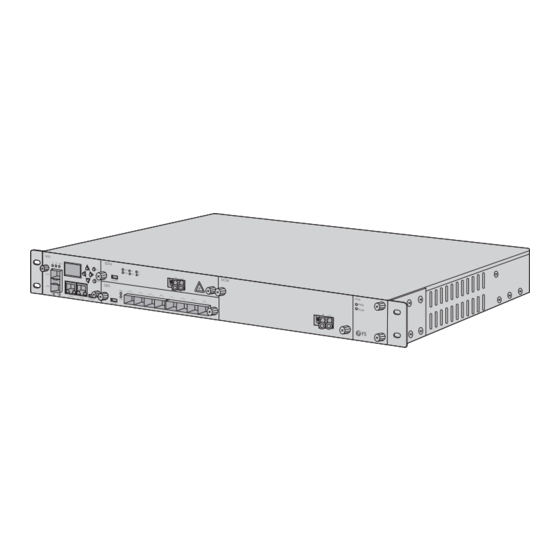
Managed Chassis Introduction Managed Chassis Item Item Name Function Main control card Fixed 1 NMU card Business card Fixed two 2-slot type or four 1-slot type FMT cards Support eld-replaceable and hot-swappable Lugs Used to x the chassis to the cabinet Power AC or DC power, hot-swappable Grounding screw... - Page 12 Provide main and daughter cards information Operation keys Used for controlling the LCD display Console port Reserved for FS future use (not available for customers) RJ45 ETH port Used for device management and program upgrade Optical transceiver Indicating the status of optical transceiver...
- Page 13 Installing Inserting FMT pluggable cards into the 4U managed chassis 1. Insert the FMT pluggable card along with the guide rail into the chassis. 2. Tighten the two loose screws on the card by your hands only. NOTE: Take 4U managed chassis installation for example. Mounting the equipment in a rack 1.
- Page 14 Connecting to the Power 1. Install the PGND cable. AC Power...
- Page 15 DC Power 2. Plug the power cord into the power port on the back of the managed chassis. 3. Connect the other end of the power cord to a power outlet. 4. Press the button to turn on the power. NOTE: 1.
- Page 16 Check Parameters of FMT Pluggable Cards Card Positions Introduction Check the Parameters When you want to see the parameters of card 3 (EDFA) in blue wireframe, you can take the following steps. Step 1: Get position of this card on LCD screen This card is in the 3rd slot.
- Page 17 Step 2: View the card Press “OK button” to enter the interface and then go on with “down key”, now you can see the Card3 Info parameters of this card. EDFA 1. Work Mode If you want to see other card parameters, press “ESC” to quit, and return back to the rst step.
- Page 18 Check the Parameters through SNMPV1 You can also check the parameters through our remote network management system. For example, the EDFA card has been inserted into the 3rd slot, then you should choose the corresponding MIB document of OAP-C3-EDFA. Otherwise you can not get the information you want. OAP-C1-EDFA.my 2017/7/3 9:40 OAP-C2-EDFA.my...
-
Page 19: Product Warranty
Product Warranty FS ensures our customers that any damage or faulty items due to our workmanship, we will o er a free return within 30 Days from the day you receive your goods. This excludes any custom made items or tailored solutions. -
Page 20: Produktübersicht
Produktübersicht Vielen Dank, dass Sie sich für die FMT-Serie von FS entschieden haben. Diese Anleitung soll Sie mit den FMT Infrastrukturmodulen vertraut machen und beschreibt, wie Sie die FMT Infrastrukturmodule in Ihrem Netzwerk einsetzen. Managed Chassis Chassis Kapazität Chassis Typ... - Page 21 FMT Infrastrukturmodule 1-Slot-Kartentyp DWDM EDFA 2-Slot-Kartentyp EYDFA OTDR HINWEIS: 1. FMT-Module sind als 1-Slot-Karte oder 2-Slot-Karte ausgelegt, um dem Managed Chassis zu entsprechen. 2. 1-Slot-Karte: OEO, DWDM EDFA, OLP, VOA, DWDM Rot/Blau-Filter, OPD, usw. 2-Slot-Karte: DCM, EYDFA, SOA, OTDR, OPM, usw.
- Page 22 Beschreibung für FMT EDFA/DCM/OEO/OLP-Steckkarten DWDM EDFA (Erbium Doped Fiber Ampli er) Kommunikations-Port Port-Name Hinweis Port-Typ Konsole Debugging- & Upgrading-Port Micro USB Glasfaser-Port Port-Name Hinweis Port-Typ Optischer Signaleingang LC/UPC Optischer Signalausgang LC/UPC Indikator Hinweis Normalzustand Alarmzustand Board Power Grünes Licht Licht aus Grünes Licht blinkt Licht aus oder blinkt Board Betrieb...
- Page 23 Tipps: DWDM EDFA kann immer noch mit einer höheren Eingangsleistung als der gesättigten Eingangsleistung arbeiten. Bitte beachten Sie jedoch, dass in diesem Fall die Leistungsprobleme auf das Risiko des Besitzers zurückzuführen sind und FS nicht für Leistungsprobleme bei der Einstellung der Eingangsleistungs-Alarmschwelle verantwortlich oder haftbar gemacht werden kann.
- Page 24 OEO Optischer Transponder Kommunikations-Port Port-Name Hinweis Port-Typ Konsole Debugging- & Upgrading-Port Micro USB Glasfaser-Port Port-Name Hinweis Port-Typ Optischer Signaleingang LC/UPC Optischer Signalausgang LC/UPC Indikator Hinweis Normalzustand Alarmzustand Board Power Grünes Licht Light o Licht aus oder blinkt Board Betrieb Licht blinkt im Sekundentakt unregelmäßig Optischer Licht aus...
- Page 25 Die wichtigsten Arbeitsparameter (1) Arbeitsmodus Normaler Modus: Wird für die Umwandlung von Fasermodus und Wellenlänge und die Regeneration des optischen Signals verwendet. Die optischen Transceiver müssen im Normalmodus paarweise verwendet werden. Zum Beispiel tritt das optische Signal in R des optischen Transceivers A1 ein und kommt dann aus T des Transceivers A2 heraus;...
- Page 26 Dispersionskompensationsmodul (DCM) Glasfaser-Port Port-Name Hinweis Port-Typ LC/UPC Optischer Signaleingang LC/UPC Optischer Signalausgang 1+1 Optical Line Protection (OLP) Kommunikations-Port Port-Name Hinweis Port-Typ Konsole Debugging- & Upgrading-Port Micro USB Glasfaser-Port Indikator Hinweis Stecker-Typ Signalempfangsport des Anwendergeräts LC/UPC Signalübertragungsport des Benutzergeräts LC/UPC Hauptport für den Empfang optischer Signale LC/UPC Hauptport zum Senden optischer Signale LC/UPC...
- Page 27 Anleitung für Bedienfeldtasten Taste Hinweis Port-Typ 3 Sekunden lang drücken, Automatikbetrieb schaltet Mode Arbeitsmodus auf manuellen Betrieb um; 1 Sekunde lang drücken, manueller Betrieb schaltet auf Automatikbetrieb um Status Arbeitskanal 3 Sekunden lang drücken, Kanäle schalten um Hinweis Normalzustand Alarmzustand (oder anderer) Board Power Grünes Licht Licht aus...
- Page 28 Die wichtigsten Arbeitsparameter (1) Arbeitsmodus Auto-Modus: Die Kanäle werden im System automatisch entsprechend der Schwelle des Switch geschaltet. Manueller Modus: Die Kanäle werden durch manuelle Einstellung des Kanals geschaltet. (2) Manuelle Kanaloption Pri Kanal (R1): Das System empfängt das optische Signal vom Kanal R1. Sec Kanal (R2): Das System empfängt das optische Signal von Kanal R2.
-
Page 29: Stromversorgung
Einführung zum Managed Chassis Managed Chassis Artikel Name Funktion Hauptsteuerkarte Fixiert eine NMU-Karte Business-Karte Fixiert zwei 2-Slot-Typ oder vier 1-Slot-Typ FMT-Karten Lüfter Unterstützt Austauschbarkeit im Feld und Hot-Swap-Fähigkeit Laschen Dient zur Befestigung des Chassis am Gehäuse Stromversorgung AC- oder DC-Stromversorgung, hot-swap-fähig Erdungsschraube Dient zur Erdung des Chassis Stromversorgung... - Page 30 Gerätestatusanzeige P1 (Power1), P2 (Power2), RUN LCD-Anzeigebildschirm Liefern Informationen zu Haupt- und Nebenkarten Bedientasten Wird zur Steuerung des LCD-Displays verwendet Reserviert für zukünftige FS-Verwendung Konsolenanschluss (nicht für Kunden verfügbar) Wird für die Geräteverwaltung und das RJ45-ETH-Port Programm-Upgrade verwendet Betriebsstatusanzeige des...
- Page 31 Installation Einsetzen von FMT-Steckkarten in das 4HE-Managed-Chassis 1. Setzen Sie die FMT-Steckkarte zusammen mit der Führungsschiene in das Chassis ein. 2. Ziehen Sie die beiden losen Schrauben an der Karte nur mit den Händen an. HINWEIS: Nehmen Sie als Beispiel die Installation eines 4HE Managed Chassis. Einbau des Geräts in ein Rack 1.
-
Page 32: Anschluss An Die Stromversorgung
Anschluss an die Stromversorgung 1. Installieren Sie das PGND-Kabel. AC-Stromversorgung... - Page 33 DC-Stromversorgung 2. Stecken Sie das Netzkabel in den Netzanschluss auf der Rückseite des Managed Chassis. 3. Schließen Sie das andere Ende des Netzkabels an eine Netzsteckdose an. 4. Drücken Sie die Taste , um das Gerät einzuschalten. HINWEIS: 1. Schalten Sie die AC/DC-Stromversorgung vor dem Anschließen aus. 2.
- Page 34 Überprüfen der Parameter von FMT-Steckkarten Kartenpositionen Prüfen der Parameter Wenn Sie die Parameter der Karte 3 (EDFA) sehen möchten, können Sie die folgenden Schritte durchführen. Schritt 1: Position dieser Karte auf dem LCD-Bildschirm abrufen Diese Karte be ndet sich im 3. Steckplatz. Bitte drücken Sie die "Abwärts-Taste" auf der rechten .
- Page 35 Schritt 2: Ansicht der Karte Drücken Sie die "OK-Taste", um die Schnittstelle aufzurufen und fahren Sie dann mit der Card3 Info "Abwärts-Taste" fort, jetzt können Sie die Parameter dieser Karte sehen. EDFA 1. Work Mode Wenn Sie andere Kartenparameter sehen möchten, drücken Sie "ESC", um zu beenden und zum ersten Schritt zurückzukehren.
- Page 36 Prüfen der Parameter über SNMPV1 Sie können die Parameter auch über unser Remote-Netzwerkmanagementsystem überprüfen. Wenn z. B. die EDFA-Karte in den dritten Steckplatz eingesetzt wurde, sollten Sie das entsprechende MIB-Dokument von OAP-C3-EDFA auswählen. Andernfalls können Sie die gewünschten Informationen nicht erhalten. OAP-C1-EDFA.my 2017/7/3 9:40 OAP-C2-EDFA.my...
- Page 37 Produktgarantie FS versichert unseren Kunden, dass wir bei Schäden oder fehlerhaften Artikeln, die auf unsere Verarbeitung zurückzuführen sind, eine kostenlose Rückgabe innerhalb von 30 Tagen ab dem Tag, an dem Sie Ihre Ware erhalten haben, anbieten werden. Dies gilt nicht für Sonderanfertigungen oder maßgeschneiderte Lösungen.
-
Page 38: Description Du Produit
Description du Produit Merci d'avoir choisi la série FS FMT. Ce guide est conçu pour vous familiariser avec les modules d'infrastructure FMT et décrit comment procéder à leur déploiement. Châssis Géré Capacité du Châssis Type de Châssis Type de Carte à 2 Rainures Type de Carte à... -
Page 39: Modules D'infrastructure Fmt
Modules d'Infrastructure FMT Type de Carte à 1 Rainure DWDM EDFA Type de Carte à 2 Rainures EYDFA OTDR REMARQUE: 1. Les modules FMT sont conçus comme des cartes à 1 ou 2 rainure(s) pour correspondre au châssis géré. 2. Carte à 1 rainure : OEO, DWDM EDFA, OLP, VOA, Filtre Rouge/Bleu DWDM, OPD, etc. Carte à... -
Page 40: Indicateur
Description Cartes En chables FMT EDFA/DCM/OEO/OLP DWDM EDFA (Ampli cateur à Fibre Dopée à l'Erbium) Port de Communication Port Description Type de Port Console Port de débogage et de mise à niveau Micro USB Port Fibre Port Description Type de Port Port d'entrée du signal optique LC/UPC Port de sortie du signal optique... -
Page 41: Paramètres De Fonctionnement Principaux
Mais veuillez noter que dans ce cas, les problèmes de performance sont aux risques et périls du propriétaire et que FS ne peut être tenu pour responsable des problèmes de performance liés au réglage du seuil d'alarme de puissance d'entrée. -
Page 42: Anormalité
Transpondeur Optique OEO Port de Communication Port Description Type de Port Console Port de débogage et de mise à niveau Micro USB Port Fibre Port Description Type de Port Port de réception du signal de l'émetteur-récepteur optique LC/UPC Port de transmission du signal de l'émetteur-récepteur optique LC/UPC Indicateur Description... - Page 43 Paramètres de Fonctionnement Principaux (1) Mode de Fonctionnement Mode Normal : Utilisé pour la conversion du mode et de la longueur d'onde de la bre, et la régénéra- tion du signal optique. Les modules optiques doivent être utilisés par paires en mode normal. Par exemple, le signal optique entre dans la partie R du module A1 et sort ensuite de la partie T du module A2 ;...
- Page 44 Module de Compensation de la Dispersion (DCM) Port Fibre Port Description Type de Port LC/UPC Port d'entrée du signal optique LC/UPC Port de sortie du signal optique Protection de Ligne Optique 1+1 (OLP) Port de Communication Port Description Type de Port Console Port de débogage et de mise à...
-
Page 45: Utilisation De La Touche
Instructions des Touches du Panneau Touches Description Utilisation de la Touche Appuyez pendant 3 secondes, le mode automatique Mode Changement de Mode de passe en mode manuel ; Fonctionnement Appuyez pendant 1 seconde, le mode manuel passe en mode automatique Changement du Canal de Appuyez pendant 3 secondes pour changer de Statut... -
Page 46: Les Paramètres De Fonctionnement Principaux
Les Paramètres de Fonctionnement Principaux (1) Mode de Fonctionnement Mode Automatique : Les canaux sont commutés automatiquement dans le système en fonction du seuil de commutation. Mode Manuel : La commutation des canaux se fait par le réglage manuel des canaux. (2) Option de Canal Manuel Canal Pri (R1) : Le système reçoit le signal optique du canal R1. -
Page 47: Introduction Aux Châssis Gérés
Introduction aux Châssis Gérés Châssis Gérés Élément Désignation Fonction Carte de contrôle principale 1 Carte NMU xe Deux cartes FMT xes à 2 rainures ou quatre cartes Carte commerciale xes FMT à 1 rainure Ventilateur Remplaçables sur site et remplaçables à chaud Embouts Utilisé... - Page 48 Fournit des informations sur les cartes Écran d'a chage LCD principales et cartes secondaires. Touches de commande Utilisé pour contrôler l'écran LCD Réservé à l'usage futur de FS Port Console (non disponible pour clients) UUtilisé pour la gestion des appareils et la Port ETH RJ45 mise à...
-
Page 49: Insertion Des Cartes En Chables Fmt Dans Le Châssis Géré 4U
Installation Insertion des cartes en chables FMT dans le châssis géré 4U 1. Insérez la carte en chable FMT le long du rail de guidage dans le châssis. 2. Serrez les deux vis de la carte. REMARQUE: Prenez l'exemple de l'installation d'un châssis géré 4U. Montage de l'équipement dans un rack 1. -
Page 50: Connexion À L'alimentation
Connexion à l'Alimentation 1. Installez le câble PGND. Courant AC... - Page 51 Courant DC 2. Branchez le câble d'alimentation sur le port d'alimentation situé à l'arrière du châssis géré. 3. Branchez l'autre extrémité du câble d'alimentation à une prise de courant. 4. Appuyez sur le bouton pour mettre l'appareil sous tension. REMARQUE: 1.
-
Page 52: Véri Cation Des Paramètres Des Cartes En Chables Fmt
Véri cation des Paramètres des Cartes En chables FMT Positions des Cartes Véri cation des Paramètres Si vous voulez consulter les paramètres de la carte 3 (EDFA), vous pouvez suivre les étapes suivantes. Étape 1 : Obtenir la position de la carte sur l'écran LCD La carte se trouve dans la 3ème rainure. - Page 53 Étape 2 : Visualisation de la carte Appuyez sur "OK" pour entrer dans l'interface, puis continuez avec "down key". Maintenant vous Card3 Info pouvez voir les paramètres de cette carte. EDFA 1. Work Mode Si vous voulez voir d'autres paramètres de la carte, appuyez sur "ESC" pour quitter et revenir à la première étape.
- Page 54 Véri er les Paramètres par SNMPV1 Vous pouvez également véri er les paramètres à travers notre système de gestion de réseau à distance. Par exemple, la carte EDFA a été insérée dans la troisième rainure, alors vous devez choisir le document MIB correspondant de OAP-C3-EDFA. Sinon, vous ne pourrez pas obtenir les informations souhaitées.
-
Page 55: Informations En Ligne
Garantie du Produit FS garantit à ses clients que tout article endommagé ou défectueux dû à sa fabrication pourra être retourné gratuitement dans un délai de 30 jours à compter de la date de réception de la marchandise. Cela exclut les articles fabriqués sur mesure ou les solutions personnalisées. -
Page 56: Compliance Information
Any changes or modi cations not expressly approved by the grantee of this device could void the user's authority to operate the equipment. Responsible party (only for FCC matter) FS.COM Inc. 380 Centerpoint Blvd, New Castle, DE 19720, United States https://www.fs.com... - Page 57 Die FS.COM GmbH erklärt hiermit, dass dieses Gerät mit der Richtlinie 2014/30/EU konform ist. Eine Kopie der EU-Konformitätserklärung nden Sie unter www.fs.com/de/company/quality_control.html FS.COM GmbH déclare par la présente que cet appareil est conforme à la Directive 2014/30/UE. Une copie de la Déclaration UE de Conformité est disponible sur https://www.fs.com/fr/company/quality_control.html FS.COM LIMITED...