Table des Matières
Publicité
Les langues disponibles
Les langues disponibles
Liens rapides
Publicité
Chapitres
Table des Matières

Manuels Connexes pour Tekno Point WINE-14


Sommaire des Matières pour Tekno Point WINE-14
- Page 1 MANUALE DI USO E INSTALLAZIONE USE MANUAL AND INSTALLATION MANUEL D’UTILISATION ET INSTALLATION Condizionatore per cantine Air conditioner for wine cellar Climatisation pour caves à vin WINE WINE-14 Rev. 1 MANUALE INSTALLAZIONE DBIS...
- Page 2 Is in compliance with the follow ECC direcrives, latest modification included, and the relevant nationale granting regulations in force: 2004/108/CE 2006/95/CE 2003/108/CE 2011/65/CE 2012/2016/CE TEKNO POINT ITALIA S.R.L. Marcon (VE), Via dell’Artigianato, 5 | 30020 Marcon VE - IT 04 Febbraio 2020 Tel. 041 5020421 | Fax 041 5029514 L’amministratore info@teknopoint.com Rocco Bolgan www.teknopoint.com...
- Page 3 ITALIANO...
-
Page 4: Table Des Matières
INDICE 1. MATERIALE CONTENUTO NELLA CONFEZIONE 2. GENERALITÀ 3. DESCRIZIONE DELLA MACCHINA a. Climatizzazione monoblocco b. controllore digitale c. sonde di misurazione temperatura/umidità d. umidificatore d’aria 4. DATI TECNICI GENERALI 5. INSTALLAZIONE a. precauzioni di sicurezza b. installazione climatizzatore c. Installazione kit di aspirazione ed espulsione aria d. -
Page 5: Materiale Contenuto Nella Confezione
Il presente manuale ha lo scopo di fornire indicazioni utili per una corretta installazione e la manutenzione del climatizzatore per cantina WINE-14, prima di procedere con qualunque attività è importante leggere con la dovuta attenzione le seguenti istruzioni in ordine: •... -
Page 6: Descrizione Della Macchina
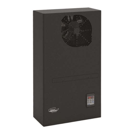
L’unità di climatizzazione WINE-14 è stata progettata e costruita in Italia assemblando prodotti commerciali ed altri realizzati in proprio ed è conforme alle norme in vigore. -
Page 7: Controllore Digitale
WINE-14 b. controllore digitale Al controllore elettronico DIXELL è affidata la gestione della temperatura e l’apporto dell’umidità, valori programmabili manualmente a piacere dal cliente. Funzionamento schiacciando il tasto azzurro di start/stop si da inizio al ciclo di funzionamento di WINE- •... -
Page 8: Sonde Di Misurazione Temperatura/Umidità
(meglio l’acquedotto) ed elettricamente alla apposita presa posta sul retro di WINE-14. L’unità prevede lo scarico dell’acqua di ogni fine ciclo non utilizzata da convogliare nello stesso recipiente di accumulo condensa del climatizzatore. Pressione acqua alimentazione: min. 1 max. 3... -
Page 9: Precauzioni Di Sicurezza
WINE-14 Compressore tipo Ermetico rotativo Batteria con alette in Scambiatori di calore alluminio tubi in rame Elettroventilatore lato cantina, portata: (mc/h) Elicoidale - 300 Elettroventilatore lato esterno tipo, (mc/h) centrifugo - 300 Dimensioni esterne... -
Page 10: Installazione Climatizzatore
WINE-14 evitare di tirare, incidere o schiacciare i cavi elettrici di alimentazione o collegamento e non • avvicinarli a fonti di calore; • non avvicinarsi alle apparecchiature con le mani bagnate. staccare la spina di alimentazione elettrica durante le operazioni di manutenzione;... -
Page 11: Installazione Kit Di Aspirazione Ed Espulsione Aria
WINE-14 LINEA TRATTEGGIATA INGOMBRO MACCHINA FASE 2 FASE 1 FASE 3 FASE 4: fissare la staffa di sostegno alla parete; controllare che la staffa sia stata montata a livello; appendere il climatizzatore; Installazione kit aspirazione espulsione aria inserire i tubi in PVC diam. - Page 12 WINE-14 • Sigillare bene, all’esterno della parete, lo spazio rima- nente tra il foro passante della parete ed il tubo in pla- stica di aspirazione ed espulsione aria con i tubi in ela- stomero nero in dotazione come da foto.
- Page 13 WINE-14 A lavoro finito avvitare la vite di sicurezza fino in fondo che fissa il monoblocco alla staffa di sostegno. Pag. 10 www.teknopoint.com...
-
Page 14: Installazione Umidificatore
WINE-14 installazione dell’umidificatore Le posizioni STD ed ottimali di montaggio dell’umidificatore sono 2: • a fianco del monoblocco all’altezza della fuori uscita dell’aria a distanza di almeno 40 cm circa (vedi schema a lato) l’ acqua NON deve essere nebulizzata contro il climatizzatore e dilavarlo;... -
Page 15: Posizionamento Sonda Di Temperatura/Umidità
WINE-14 Note -spurgare il tubo di alimentazione d’acqua prima di collegarlo all’umidificatore; -con l’installazione dell’umidificatore su pareti e paretine in laterizio si potrebbero amplificare vibrazioni e rumorosità che non vengono evidenziate se la parete è stata realizzata in materiale più... -
Page 16: Vista Di Assieme
WINE-14 fusibile F2-F3: rimuovere “il mantello” esterno del climatizza- tore utilizzando la chiave a brugola in dotazione e successivamente rimuovere con un cacciavite a croce la lamiera di protezione parti elettriche svitando le due viti evidenziate dalle frecce rosse. (foto 2... - Page 17 WINE-14 Pag. 14 www.teknopoint.com...
-
Page 18: Manutenzione Ordinaria
WINE-14 7. MANUTENZIONE ORDINARIA il climatizzatore WINE-14 non necessità di particolari attenzioni ma solo delle normali operazioni di pulizia che comunque in assenza potrebbero alterarne il normale funzionamento in particolare bisogna provvedere quando serve: alla pulizia dei due filtri aria;... - Page 19 WINE-14 8. DIAGNOSTICA Durante il funzionamento possono verificarsi degli inconvenienti: descrizione problema possibili cause soluzione verificare: spina, presa, fusibili, il climatizzatore non si accende manca tensione elettrica linea elettrica il climatizzatore con display è stata raggiunta la temperatura...
-
Page 20: Riciclaggio E Fine Della Durata Dei Prodotti
Le specifiche di sicurezza devono essere sempre conformi alle disposizioni di legge vigenti. In particolare il prodotto WINE-14 è composto da materiali riciclabili all’80%: carta, cartone, polistirolo, legno, plastica, gomma isolante;... -
Page 21: Schema Elettrico
WINE-14 10. SCHEMA ELETTRICO Pag. 18 www.teknopoint.com... -
Page 22: Schema Generale Collegamenti
WINE-14 11. SCHEMA GENERALE COLLEGAMENTI 12. MISURE INGOMBRO CLIMATIZZATORE Pag. 19 www.teknopoint.com... -
Page 23: Dima Di Foratura
WINE-14 13. DIMA DI FORATURA La confezione contiene anche una dima di foratura scala 1:1 Pag. 20 www.teknopoint.com... -
Page 24: Precauzioni Di Sicurezza
rel 1.0 - 11.02.205 - Cod.1591004100 Manuale di istruzione 4. DIMENSIONI XH10P - XH15P Le dimensioni della sonda di umidità sono illustrate nel disegno seguente. Sonda di umidità relativa con uscita 4÷20mA o 0÷10Vdc (30÷90%) XH20P - XH25P Ø 3÷6mm Sonda di umidità... - Page 25 4.2 DEUMIDIFICAZIONE SENZA RELÈ DEUMIDIFICATORE (OA1 DIVERSO DA DEH) – XH260L – XH260V FUNZIONAMENTO STANDARD In questo caso la deumidificazione si effettua IMPOSTANDO i parametri: tHu = c-H tipo di umidificazione con relè caldo e freddo CONTROLLORE DI TEMPERATURA E UMIDITÀ oA1 diverso da dEH: Si attivano contemporaneamente le uscite caldo e compressore quando l’umidità...
-
Page 26: Lista Dei Parametri
COMBINAZIONI DI TASTI 6.6 PER CAMBIARE IL VALORE DI UN PARAMETRO Per cambiare il valore di un parametro: Accedere al modo programmazione, Premuti per 3 sec. bloccano e sbloccano la tastiera Selezionare il parametro desiderato. Premere il tasto SET_RH, il suo valore inizia a lampeggiare Per entrare in programmazione Modificarlo con i tasti o e n . -
Page 27: Installazione E Montaggio
8.1 FUNZIONE MICRO PORTA (i1F=dor) VENTILATORI Segnala al dispositivo l’apertura della porta della cella. Quando la porta viene aperta il comportamento Funzionamento ventilatori: C-n : In parallelo ai carichi, spenti in sbrinamento.; delle varie uscite è stabilito dal parametro “odc” : C-y : In parallelo ai carichi, accesi in sbrinamento. -
Page 28: Dati Tecnici
XH260V: a pannello su foro 56x72 mm. con viti 3 x 2mm distanza tra i fori 40mm. 9.3 DIMA DI FORATURA XH260V Grado protezione: IP20. Grado protezione frontale: IP65 con guarnizione frontale mod. RG-L (XH260L); RGW-V (XH260V). Connessioni: morsettiera a vite per conduttori 2,5 mm resistenti al calore per parte a bassissima tensione Faston maschi 6,3 mm resistenti al calore per parte a bassa tensione (110 o 230Vac) - Page 29 Esclusione all. temp. dopo porta aperta 0 ÷ 250 minuti Configurazione degli allarmi di umidità rE = relativi / Ab = assoluti Allarme di minima umidità 0 ÷ 50 / Lci ÷ AHu Allarme di massima umidità 0 ÷ 50 / AHL ÷ uci Isteresi per il rientro allarme di umidità...
-
Page 31: Caratteristiche Tecniche
1. Caratteristiche tecniche 1.1. Tabella dati tecnici Capacità di polverizzazione Capacità di polverizzazione 1 L/ora a 50 Hz, 1.2 L/ora a 60 Hz Capacità di polverizzazione Capacità di polverizzazione Alimentazione elettrica Alimentazione elettrica 230 V, 50/60 Hz Alimentazione elettrica Alimentazione elettrica Potenza nominale Potenza nominale 34 W a 50 Hz, 39 W a 60 Hz... -
Page 32: Norme Generali Di Sicurezza
2. Introduzione Il mini NEB è un umidificatore d’aria e funziona secondo il principio della polverizzazione dell’acqua per forza centrifuga. L’apparecchio dev’essere alimentato con acqua di rete idrica o demineralizzata. Per un corretto funzionamento della macchina è importante attenersi alle regole d'installazione di seguito descritte in questo manuale. -
Page 33: Operazioni Preliminari
3. Installazione 3.1. Operazioni preliminari Per rendere operativo il mini NEB è necessario disporre di: • rete elettrica a 230 V, 50/60 Hz con terra e dispositivi di protezione; • collegamento per l’acqua di alimentazione; • collegamento per lo scarico dell’acqua L’installazione deve soddisfare i requisiti di sicurezza previsti dalle normative locali vigenti. -
Page 34: Collegamenti Elettrici
3.3. Collegamenti elettrici 3.3.1. Schema elettrico 1 1 1 1 Motore umidificatore 2 2 2 2 Interruttore di livello 3 3 3 3 Elettrovalvola 4 4 4 4 Ponte umidostato esterno Condensatore 5 5 5 5 ~ 275 V, 0.22 µF, classe X2 Umidostato esterno 230 V, A A A A 50/60 Hz, 0.2 A (opzionale) -
Page 35: Collegamenti Idraulici
3.4. Collegamenti idraulici L’installazione dell’umidificatore prevede l’allacciamento alle tubazioni di alimento e di drenaggio dell’acqua. I tubi, forniti di serie con l’umidificatore, devono essere collegati come di seguito descritto Il tubo di alimentazione A, fornito di serie, presenta alle due estremità... - Page 36 • Eseguire sul muro n.3 fori diametro 6mm e profondità 30mm, come mostrato in Fig. 3.5.2; • pulire l’interno dei fori; • inserire i tre tasselli tenendo le due alette di espansione sul piano verticale;fissare la staffa con le tre viti. •...
- Page 37 4. Avviamento, controllo, arresto 4.1. Verifiche Prima di mettere in funzione l’umidificatore verificare i seguenti punti: • tutti i collegamenti, sia elettrici che idraulici, devono essere fatti secondo quanto riportato in questo manuale; • non deve esserci alcuna perdita d’acqua nel circuito; •...
-
Page 38: Pulizia Del Filtro Dell'aria
5.2. Pulizia del filtro dell’aria Fig. Fig. Fig. Fig. 5.2 5.2..1 1 1 1 - - - - Smontaggio del filtro Smontaggio del filtro Smontaggio del filtro Smontaggio del filtro Il filtro deve essere pulito periodicamente, in quanto l’accumularsi dello sporco e della polvere, riduce la portata d’aria e quindi l’efficienza della macchina. -
Page 39: Smaltimento Del Prodotto
5.3. Ispezione e pulizia del sifone di scarico Potrebbe essere necessario pulire periodicamente il sifone di scarico R di Fig. 5.3.1 in quanto un accumulo di sporco, al suo interno, potrebbe comprometterne il buon funzionamento. Quando si rende necessario la pulizia fare quanto segue: •... -
Page 40: Problemi E Soluzioni
etc.) dalle parti metalliche (staffa motore, staffa a muro, etc…). Rimuovere il cablaggio dalla macchina e provvedere allo smaltimento secondo le norme vigenti. 7. Dispositivi opzionali 7.1. Umidostato di controllo Il mini NEB è predisposto per il montaggio dell’umidostato di controllo che accende l’umidificatore solo quando il valore dell’umidità... - Page 41 ENGLISH...
- Page 42 INDEX 1. MATERIALS CONTAINED IN THE PACKAGE 2. GENERAL 3. DESCRIPTION OF THE MACHINE a. Monoblock air conditioning b. digital controller c. temperature / humidity measuring probes d. air humidifier 4. GENERAL TECHNICAL DATA 5. INSTALLATION a. safety precautions b. air conditioner installation c.
-
Page 43: Materials Contained In The Package
2. GENERAL The purpose of this manual is to provide useful information for correct installation and maintenance of the WINE-14 cellar air conditioner, before proceeding with any activity it is important to read the following instructions carefully: • compliance with the safety regulations in force concerning the installation of electrical and refrigeration systems;... -
Page 44: Description Of The Machine
3. DESCRIPTION OF THE MACHINE The WINE-14 air conditioning unit, which consists of the monoblock air conditioner and the humidifier, has been designed and built to be installed in the cellar with the aim of preserving, refining and optimally aging the wine in cask and / or bottle. -
Page 45: Digital Controller
Operation • pressing the blue start / stop button starts the WINE-14 operating cycle; in this phase the temperature and humidity values are read inside the cellar and it is therefore possible to program the desired temperature and humidity;... -
Page 46: Temperature / Humidity Measuring Probes
(better the aqueduct) and electrically to the appropriate socket on the back of WINE-14. The unit foresees the unloading of water for each unused end of the cycle to be conveyed in the same condensation container of the air conditioner. -
Page 47: Safety Precautions
WINE-14 Battery with Heat exchangers aluminum fins copper tubes Cell side electric fan, flow rate: (mc/h) Helical - 300 External side electric fan type, (mc/h) centrifugal - 300 External dimensions 456 x 289 x h 822... -
Page 48: Air Conditioner Installation
WINE-14 • avoid spraying flammable sprays directly against the air conditioner because fire can occur; • do not cover the air conditioner; • avoid that the humidity inside the room is not more than 90% because humidity could form on... - Page 49 WINE-14 STEP 4: fix the support bracket to the wall; check that the bracket has been mounted on level; hang up the air conditioner; Installation of air expulsion suction kit - insert the PVC pipes diam. 125, female side, from the outside of the wall to the male attachment on the machine;...
- Page 50 WINE-14 If the compressor stops due to overtemperature, temporarily remove the external grilles mounted on the air intake and exhaust pipes. When the work is finished, screw the safety screw all the way in, fixing the block to the support bracket.
-
Page 51: Humidifier Installation
WINE-14 humidifier installation There are 2 STD and optimal humidifier mounting positions: • next to the monobloc at the height of the air out- let at a distance of at least about 40 cm (see dia- gram opposite) the water must NOT be sprayed against the air conditioner and washed away;... -
Page 52: Power Supply And Humidifier Connection To The Air Conditioner
WINE-14 Note - bleed the water supply hose before connecting it to the humidifier; - with the installation of the humidifier on walls and brick walls, it is possible to amplify vibrations and noise that are not highlighted if the wall has been made of a more "compact" material;... -
Page 53: Overall View
WINE-14 overall view This is a photographic representation of a typical installation of a WINE-14 air conditioner with all its accessories. • Monoblock positioned 200 mm from the ceiling; • The humidifier is present as soon as it is centered;... -
Page 54: Routine Maintenance
WINE-14 6. ROUTINE MAINTENANCE the WINE-14 air conditioner does not need particular attention but only the normal cleaning operations that in any case in absence could alter its normal functioning in particular, it is necessary to provide when needed: •... -
Page 55: Diagnostics
WINE-14 7. DIAGNOSTICS problem description possible causes solution the air conditioner does not no electricity supply check: plug, socket, fuses, switch on power line the air conditioner with the the set temperature has been... -
Page 56: Recycling And End Of The Duration Of The Products
Ensure that hazardous substances are disposed of safely and that appropriate personal protective equipment is used. The safety specifications must always comply with the laws in force. In particular, the WINE-14 product is composed of 80% recyclable materials: • paper, cardboard, polystyrene, wood, plastic, insulating rubber;... -
Page 57: Electrical Diagram
WINE-14 ELECTRICAL DIAGRAM Pag. 16 www.teknopoint.com... -
Page 58: General Wiring Diagram
WINE-14 9. GENERAL WIRING DIAGRAM 12. MEASUREMENTS OF AIR CONDITIONING Pag. 17 www.teknopoint.com... - Page 59 WINE-14 13. DRESSING TEMPLATE The package also contains a 1: 1 scale drilling template Pag. 18 www.teknopoint.com...
-
Page 60: Dimensions
rel 1.0 - 18/07/2016 - Cod.1592004100 By means of the proper holes, fix the probe where it has to measure the Installation and Operating Instructions 4. DIMENSIONS humidity IMPORTANT NOTE: To avoid having problem with condensing place the probe The dimensions of the humidity probe are the following: XH10P - XH15P with filter in a horizontal position or turn down. - Page 61 4.2.1 Relation between cooling, heating and dehumidifying XH260L – XH260V If is simultaneously present a request of cooling (temp>SET_TEMP+dbt) and dehumidifying (RH > SET_RH+dbH): the cooling action has the priority over the dehumidifying action: only the compressor relay is energised till the SET_TEMP is reached at this point also the heating relay is enabled.
-
Page 62: Temperature Display
NOTE: the new programming is stored even when the procedure is exited by waiting the time-out. 6.1 ICONS AND SYMBOLS 6.7 HOW TO LOCK THE KEYBOARD Each LED function is described in the following table. LED2 LED3 Keep the o and n keys pressed together for more than 3 s the o and n keys. The “POF”... -
Page 63: Installation And Mounting
ALd Temperature alarm delay: (0÷255 min) time interval between the detection of an alarm condition If the nPS activation in the did time is reached, switch off and on the instrument to restart normal regulation. and the corresponding alarm signalling. dAO Delay of temperature alarm at start-up: (0min÷23h 50min) time interval between the detection of 8.5 HEATING RELAY SAFETY (i1F=Ht) the temperature alarm condition after the instrument power on and the alarm signalling. -
Page 64: Alarm Signalling
12. ALARM SIGNALLING 15. DEFAULT SETTING VALUES Message Cause Outputs Label Value Menu Description Range Set T “P1” Thermostat probe failure Compressor and heating outputs off - - - Temperature Set Point LS ÷ uS ( nu = temperature regulation disabled ) “P2”... -
Page 66: Technical Features
1. Technical features 1.1. Technical data table Atomization Capacity Atomization Capacity Atomization Capacity Atomization Capacity 1 L/hour at 50 Hz, 1.2 L/hour at 60 Hz Power Supply Power Supply Power Supply Power Supply 230 V, 50/60 Hz Nominal Power Nominal Power Nominal Power Nominal Power 34 W at 50 Hz, 39 W at 60 Hz... -
Page 67: General Safety Rules
2. Introduction The MININEB is a room humidifier, working by the principle of atomizing water by mean of centrifugal force. The machine must be feeded by tap water or fully demineralized water. For a correct functioning of the machine, it’s very important to follow the below installation rules. 2.1. -
Page 68: Preliminary Operations
3. Installation 3.1. Preliminary operations To put in operation the MININEB it’s necessary to have : • Electrical Power Supply 230V/60Hz grounded and with protection devices. • Water supply connection • Water Drain connection The installation must comply the requisites provided by the local safety regulations. 3.2. -
Page 69: Electrical Wiring Diagram
3.3. Electical connections 3.3.1. Electrical wiring diagram 1 1 1 1 Humidifier motor 2 2 2 2 Floating switch 3 3 3 3 Solenoid Valve 4 4 4 4 External Humidistat Bridge Condenser 5 5 5 5 ~ 275 V, 0.22 F, X2 class External Humidistat 230V, A A A A 50/60 Hz, 0,2A (Optional) -
Page 70: Hydraulic Connections
3.4. Hydraulic connections The installation of the machines requires the connections to the hoses for water feeding and discharge. The hoses, included with the humidifier, must be fitted as described below. The water supply hose A, supplied as standard, has on both extremities a threaded bush G ¾. - Page 71 • Make three holes diameter 6mm and 3mm deep on the wall, as in Pic. 3.5.2; Clean the holes internally. Insert the three screw anchors keeping the espansion fins on the vertical plane; fasten the bracket with the three screws. •...
-
Page 72: Switch Off
4. Startup, control and switch off. 4.1. Checks Before starting the humidifier, check the following points: • All connections, both electrical and hydraulic, must be made as is written in the present manual. • There must be no water dripping in the circuit. •... -
Page 73: Air Filter Cleaning
5.2. Air filter cleaning Pic..5.2 5.2..1 1 1 1 – – – – Air filter disa Air filter disa Air filter disa Air filter disassemble ssemble ssemble ssemble The air filter must be periodically cleaned, as the continuous accumulation of dirt and dust progressively reduce the air flow, and consequently the efficiency of the machine. -
Page 74: Solenoid Valve
5.3. Inspection and Cleaning of the Discharge Siphon It may be necessary to clean periodically the water discharge siphon R (see: Pic. 5.3.1) as the accumulation of dirt inside may compromise its correct and efficient operation. When a cleaning is necessary, see the following steps: •... -
Page 75: Product Disposal
6.3. Product disposal The machine is mainly composed of plastic components, and some metal parts, both recyclable. Before disposing of it, separate the plastic parts (body, cover, grille, etc.) from the metal ones (motor bracket, wall installation bracket, etc.). Remove the electrical cabling and dispose of it as by standard regulations 7. - Page 76 FRANÇAIS...
- Page 77 INDEX 1. MATÉRIEL CONTENU DANS LE PAQUET 2. GÉNÉRALE 3. DESCRIPTION DE LA MACHINE a. Climatisation monobloc b. contrôleur numérique c. sondes de mesure de température / humidité d. humidificateur d'air 4. DONNÉES TECHNIQUES GÉNÉRALES 5. INSTALLATION a. précautions de sécurité b.
-
Page 78: Matériel Contenu Dans Le Paquet
GÉNÉRALE Ce manuel est destiné à fournir des informations utiles pour l'installation et l'entretien corrects du climatiseur de cave WINE-14, avant de procéder à toute activité, il est important de lire attentivement les instructions suivantes dans l'ordre: • respect des réglementations de sécurité en vigueur concernant l'installation des systèmes électriques et des réfrigérateurs;... -
Page 79: Description De La Machine
à des personnes et / ou des choses en raison du non-respect de ces instructions ou de la non- utilisation d'un personnel non qualifié. L'unité de climatisation WINE-14 a été conçue et construite en Italie en assemblant des produits commerciaux et autres fabriqués par elle-même et est conforme aux réglementations en vigueur. -
Page 80: Contrôleur Numérique
• en appuyant sur le bouton bleu marche / arrêt, vous démarrez le cycle de fonctionnement du WINE-14 dans cette phase, vous pouvez lire les valeurs de température et d'humidité à l'intérieur de la cave et il est donc possible de programmer la température et l'humidité... -
Page 81: Humidificateur D'air
L'humidificateur à eau pulvérisée adiabatique apporte le% d'humidité manquante requis par le contrôleur numérique. Il doit être connecté au réseau d'eau (mieux l'aqueduc) et électriquement à la prise spéciale à l'arrière du WINE-14. L'unité prévoit l'évacuation de l'eau de chaque fin de cycle inutilisée pour être acheminée vers le même réservoir de stockage de condensation du... -
Page 82: Précautions De Sécurité
WINE-14 Type de compresseur Rotatif hermétique Échangeurs de chaleur Batterie avec ailettes en aluminium et tuyaux en cuivre Hélicoïdal - 300 Ventilateur électrique côté cave, capacité: (mc/h) Type de ventilateur électrique latéral centrifuge - 300... -
Page 83: Installation De Climatisation
WINE-14 • débrancher la fiche d'alimentation pendant les opérations de maintenance; • éviter d'utiliser de l'eau pour nettoyer le climatiseur qui pourrait s'infiltrer et provoquer un court- circuit; • éviter de pulvériser des vaporisateurs inflammables directement contre le climatiseur car des incendies peuvent se produire;... -
Page 84: Dimension De La Machine À Ligne Dashed
WINE-14 DIMENSION DE LA MACHINE À LIGNE DASHED ÉTAPE 2 ÉTAPE 1 ÉTAPE 3 ÉTAPE 4: - fixer le support au mur; - vérifier que le support a été monté de niveau; - suspendre le climatiseur;... - Page 85 WINE-14 ed il tubo plastique pour l'entrée et l'expulsion d'air avec les tuyaux en élastomère noir fournis comme indiqué sur la photo. • • • Bien sceller, à l'extérieur du mur, l'espace re- stant entre le trou traversant du mur et le tuyau d'admission et d'expulsion d'air en plastique avec les tuyaux en élastomère noir fournis comme indi-...
-
Page 86: Installation De L'humidificateur
WINE-14 Installation de l'humidificateur • positions STD et montage optimales de l'humidificateur sont 2: • • à côté du bloc-cylindres à la hauteur de la sortie d'air à une distance d'au moins 40 cm (voir schéma sur le côté), l'eau ne doit PAS être projetée contre le climatiseur et... -
Page 87: Positionnement De La Sonde De Température / Humidité
WINE-14 Note - purger le tuyau d'arrivée d'eau avant de le raccorder à l'humidificateur; - avec l'installation de l'humidificateur sur les murs et murs de briques, les vibrations et le bruit pourraient être amplifiés qui ne sont pas mis en évidence si le mur était fait d'un matériau plus "compact";... -
Page 88: F3 - Fusible De Protection Du Contrôleur Numérique: F4A (Si Présent)
F3 - fusible de protection du contrôleur numérique: F4A (SI PRÉSENT) vue d'ensemble Il s'agit d'une représentation photographique d'une installation typique d'un climatiseur WINE-14 avec tous ses accessoires. • Monobloc positionné à environ 200 mm du plafond; • Juste en dessous du centre se trouve l'humidificateur;... - Page 89 WINE-14 Pag. 13 www.teknopoint.com...
-
Page 90: Maintenance Ordinaire
WINE-14 5. MAINTENANCE ORDINAIRE • le climatiseur WINE-14 ne nécessite aucune attention particulière mais uniquement les opérations de nettoyage normales qui, en l'absence, pourraient altérer son fonctionnement normal, en particulier il est nécessaire de fournir en cas de besoin: •... -
Page 91: Des Problèmes Peuvent Survenir Pendant Le Fonctionnement
WINE-14 (3) après avoir retiré le boîtier extérieur, faites attention au câ- ble de terre, pour accéder à la partie inférieure de la batterie chaude, dévissez les 8 vis marquées du no. 3, nettoyez les ailettes avec une brosse et un aspirateur et remontez tout. -
Page 92: Recyclage Et Fin De Vie Du Produit
Les spécifications de sécurité doivent toujours être conformes aux dispositions légales en vigueur. En particulier, le produit WINE-14 est composé à 80% de matières recyclables: • papier, carton, polystyrène, bois, plastique, caoutchouc isolant;... -
Page 93: Schéma Électrique
WINE-14 7. SCHÉMA ÉLECTRIQUE Pag. 17 www.teknopoint.com... -
Page 94: Schéma Général De Connexion
WINE-14 8. SCHÉMA GÉNÉRAL DE CONNEXION 12. DIMENSIONS DE CLIMATISATION Pag. 18 www.teknopoint.com... -
Page 95: Modèle De Forage
WINE-14 13. MODÈLE DE FORAGE Le package contient également un gabarit de forage à l'échelle 1: 1 Pag. 19 www.teknopoint.com... -
Page 96: Les Spécifications Suivantes Doivent Être Lues Avant
rel 1.0 - 18/07/2016 - Cod.1592004100 2. Au moyen des trous appropriés, fixez la sonde là où elle doit mesurer la Instructions d'installation et d'utilisation humidité . 4. DIMENSIONS REMARQUE IMPORTANTE: pour éviter tout problème de condensation, Les dimensions de la sonde d'humidité sont les suivantes: XH10P - XH15P placez la sonde avec filtre en position horizontale ou baisser. -
Page 97: Contrôleur De Température Et D'humidité
4.2.1 Relation between cooling, heating and dehumidifying XH260L – XH260V 1. Si est présent simultanément une demande de refroidissement (temp> SET_TEMP + dbt) et de déshumidification (RH > SET_RH + dbH): l'action de refroidissement a la priorité sur l'action de déshumidification: seul le relais du compresseur est alimenté... - Page 98 NOTE: the new programming is stored even when the procedure is exited by waiting the time-out. 6.1 ICÔNES ET SYMBOLES Chaque fonction LED est décrite dans le tableau suivant. 6.7 HOW TO LOCK THE KEYBOARD LED2 LED3 Keep the o and n keys pressed together for more than 3 s the o and n keys. The “POF”...
-
Page 99: Installation Et Montage
Si l'activation nPS dans le temps écoulé est atteinte, éteignez et rallumez l'instrument pour redémarrer ALd Temporisation d'alarme de température: (0 ÷ 255 min) intervalle de temps entre la détection d'une condition d'alarme et la signalisation d'alarme correspondante. la régulation normale. EdA Retard d'alarme à... -
Page 100: Signalisation D'alarme
12. SIGNALISATION D'ALARME 15. DEFAULT SETTING VALUES Message Cause Outputs Label Value Menu Description Range Défaillance de la sonde Sorties compresseur et chauffage désactivées Set T Point de consigne de température “P1” - - - LS ÷ uS ( nu = temperature onde de l'évaporateur Dégivrage et par temps regulation disabled ) -
Page 102: Caractéristiques Techniques
1. Caractéristiques techniques 1.1. Tableau des données techniques Atomization Capacity Atomization Capacity Atomization Capacity Atomization Capacity 1 L/hour at 50 Hz, 1.2 L/hour at 60 Hz Power Supply Power Supply Power Supply Power Supply 230 V, 50/60 Hz Nominal Power Nominal Power Nominal Power Nominal Power... -
Page 103: Règles Générales De Sécurité
2. Introduction Le MININEB est un humidificateur d'ambiance fonctionnant selon le principe de l'atomisation de l'eau au moyen de la force centrifuge. La machine doit être alimentée par de l'eau du robinet ou de l'eau entièrement déminéralisée. Pour un bon fonctionnement de la machine, il est très important de suivre les règles d'installation ci-dessous. -
Page 104: Opérations Préliminaires
3. Installation 3.1. Opérations préliminaires Pour mettre en service le MININEB il faut disposer: • • Alimentation électrique 230V / 60Hz mise à la terre et avec des dispositifs de protection. • • Connexion d'alimentation en eau • • Connexion de vidange d'eau L'installation doit répondre aux exigences prévues par les réglementations locales de sécurité. -
Page 105: Connections Electriques
3.3. Connections electriques 3.3.1. Schéma de câblage électrique 1 1 1 1 Moteur d'humidificateur 2 2 2 2 Floating switch 3 3 3 3 Solenoid Valve 4 4 4 4 External Humidistat Bridge Condenser 5 5 5 5 ~ 275 V, 0.22 F, X2 class External Humidistat 230V, A A A A 50/60 Hz, 0,2A (Optional) -
Page 106: Connexions Hydrauliques
L'installation des 3.4. Connexions hydrauliques machines nécessite des connexions aux tuyaux pour l'alimentation et l'évacuation de l'eau. Les tuyaux, fournis avec l'humidificateur, doivent être montés comme décrit ci-dessous. Le tuyau d'alimentation en eau A, fourni en standard, a sur les deux extrémités une douille filetée G ¾. -
Page 107: Raccrocher L'installation
• Faites trois trous de diamètre 6 mm et 3 mm de profondeur sur le mur, comme sur la photo. 3.5.2; Nettoyez les trous à l'intérieur. Insérez les trois ancrages à vis en maintenant les ailettes d'expansion sur le plan vertical; fixez le support avec les trois vis. - Page 108 4. Démarrage, contrôle et arrêt. 4.1. Chèques Avant de démarrer l'humidificateur, vérifiez les points suivants: • Toutes les connexions, électriques et hydrauliques, doivent être effectuées comme indiqué dans le présent manuel. • Il ne doit pas y avoir de gouttes d'eau dans le circuit. •...
-
Page 109: Nettoyage Du Filtre À Air
5.2. Nettoyage du filtre à air Pic..5.2 5.2..1 1 1 1 – – – – Air filter disa Air filter disa Air filter disa Air filter disassemble ssemble ssemble ssemble Le filtre à air doit être nettoyé périodiquement, car l'accumulation continue de saletés et de poussières réduit progressivement le débit d'air, et par conséquent l'efficacité... -
Page 110: Inspection Et Nettoyage Du Siphon De Décharge
5.3. Inspection et nettoyage du siphon de décharge Il peut être nécessaire de nettoyer périodiquement le siphon d'évacuation d'eau R (voir: Fig. 5.3.1) car l'accumulation de saleté à l'intérieur peut compromettre son fonctionnement correct et efficace. Lorsqu'un nettoyage est nécessaire, consultez les étapes suivantes: •... -
Page 111: Élimination Du Produit
6.3. Élimination du produit La machine est principalement composée de composants en plastique et de certaines pièces métalliques, toutes deux recyclables. Avant de le jeter, séparez les pièces en plastique (corps, couvercle, grille, etc.) des pièces métalliques (support moteur, support mural, etc.). Retirez le câblage électrique et éliminez-le conformément aux réglementations standard 7. - Page 112 TEKNO POINT ITALIA S.R.L. Con l’obbiettivo di offrire comfort e qualità della vita Via dell’Artigianato, 5 | 30020 Marcon (VE) - Italy per tutti i tipi di ambienti, TEKNO POINT sviluppa Tel. 041 5020421 | Fax 041 5029514 info@teknopoint.com soluzioni innovative di climatizzazione applicabili ad www.teknopoint.com...