Publicité
Les langues disponibles
Les langues disponibles
Liens rapides
The illustrations in this document are generic; your control appearance may be slightly different from the ones shown.
Electrical wiring must be done by qualified personnel in accordance with all applicable codes and standards.
Before connecting wires, unplug the unit or switch power off at service panel and lock service disconnecting
means to prevent power from being switched on accidentally. Always wear safety glasses and gloves while
performing these instructions.
If ducts have to go through an unconditioned space (e.g.: attic), always use insulated ducts to prevent condensation
formation inside and outside ducts, which could cause material damage and/or mold growth. Moreover, if fresh air
to building duct and/or stale air from building duct goes/go through an unconditioned space, the unit must be set
to operate continuously in cold conditions (below 10°C/50°F). Continuous air movement inside ducts will prevent
condensation formation. The unit can be stopped temporarily for maintenance and/or repair purposes in such
conditions. (Refer to section 2.2 from unit User and Installer Manual for more details.)
INSTALLATION
Unplug the ventilation unit.
NOTE: If the control is to be installed in an electric box, go to step
Cut a 2
7
/
" x 1¾" hole in a wall, at a
8
convenient location for the control.
Route a cable (type 22/4) for the
control from the unit to this hole. See
figure at right.
Temporarily place the control over the
hole and mark both mounting screw hole
positions.
Remove the control, drill both screw
holes (3/16" Ø) in wall and insert the wall
anchors (included).
Strip the end of the cable to access the 4 wires (about 3"). Strip the
end of each wire (about 1/4"). Connect the wires to the terminals,
regardless of the wire color. Note which wire color has been
chosen for each terminal. See illustration below.
Mount the control to the wall.
Perform
the
electrical
connector of the unit, as shown below. For more details, refer to
the installation manual of the ventilation unit.
NOTE: To avoid miswiring, refer to the notes taken at step
to match the wire color with the right terminal.
I
U
NSTALLATION AND
READ AND SAVE THESE INSTRUCTIONS
Ø 3/16", typ.
VC0213A
12V
D-
D+
Gnd
VC0214
connection
to
the
G
A
SER
UIDE FOR
UTOMATIC
!
WARNING
CAUTION
.
VC0235
Plug the ventilation unit and test the wall control.
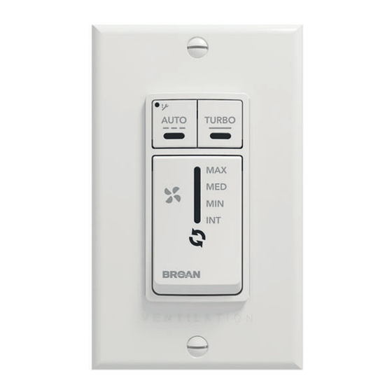
HOW TO USE THE CONTROL
VC0184
RECIRC: Recirculate air inside the house at MAX speed. Not
available on all units.
INT: Within a one hour period, the system will operate in MIN speed
for 20 minutes.
MIN/MED/MAX: Continuous exchange ventilation at selected
•
Press the TURBO button to get 4 hours of ventilation in MAX
speed. The TURBO indicator will light up. Once the 4-hour
period is done, the system will operate according to the previous
setting.
•
Press the AUTO button to let the system operate according to
outdoor temperature. The AUTO indicator will light up. The AUTO
indicator will light up and the system will operate as follows:
• Less than -25°C = 10 min/hr
• -25°C to -7°C = 20 min/hr
• 10°C to 25°C = MIN speed
• 25°C to 28°C = 30 min/hr
• 28°C to 33°C = 20 min/hr
• Above 33°C = 10 min/hr
•
If the maintenance indicator is lit, it means that the filter needs
to be cleaned or replaced. Once the filter is cleaned or replaced,
press the AUTO button for five seconds to reset the maintenance
indicator. If the maintenance indicator flashes, the LCD screen
terminal
on the unit will give the error code. Refer to the Troubleshooting
section in the ventilation unit user guide for more information.
•
At unit first boot, AUTO and TURBO indicators blink alternately
for about 1 minute. If indicators continue blinking after this period,
it means that the communication cannot be established with the
ventilation unit. Make sure wires are correctly connected to the
wall control and unit terminals (refer to step 7).
C
ONTROL
The main button works following this
sequence:
• Click 1 = RECIRC (if available)
• Click 2 = INT
• Click 3 = MIN
• Click 4 = MED
• Click 5 = MAX
• Click 6 = OFF
• and so on
The indicator lights up as per the selected
mode.
speed.
12V
D-
D+
Gnd
23842 rev. 03
Publicité

Manuels Connexes pour Venmar 41404


Sommaire des Matières pour Venmar 41404
- Page 1 NSTALLATION AND UIDE FOR UTOMATIC ONTROL READ AND SAVE THESE INSTRUCTIONS The illustrations in this document are generic; your control appearance may be slightly different from the ones shown. WARNING Electrical wiring must be done by qualified personnel in accordance with all applicable codes and standards. Before connecting wires, unplug the unit or switch power off at service panel and lock service disconnecting means to prevent power from being switched on accidentally.
- Page 2 ’ ’ UIDE D INSTALLATION ET D UTILISATION DE LA COMMANDE AUTOMATIQUE VEUILLEZ LIRE ET CONSERVER CES DIRECTIVES Les illustrations de ce document sont générales; l’apparence de votre commande peut légèrement différer de celles-ci. AVERTISSEMENT Le branchement électrique doit être effectué par du personnel qualifié conformément aux codes et aux standards en vigueur.