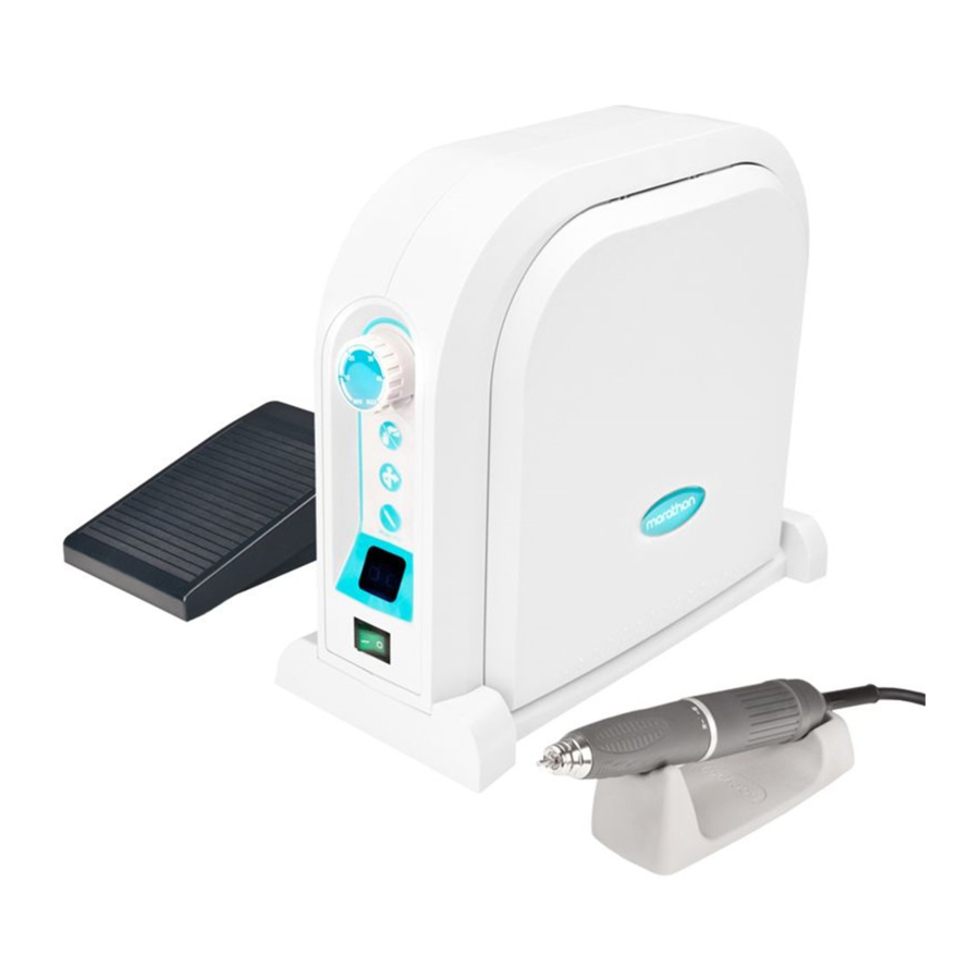
Sommaire des Matières pour Marathon Mutti 600
- Page 1 arathon utti6oo MANUAL GEBRAUCHSANWEISUNG MANUEL UTILISATEUR DU MANUAL DE USUARIO MULTI saeyang...
- Page 2 Read this User's Manual thoroughly for safety before preparing the unit for use. Lesen Sie bitte zur Sicherheit diese Gebrauchsanweisung sorgfaltig durch, bevor Sie das Gerat auf den Erstgebrauch vorbereiten Lisez attentivement ce manuel utilisateur par precaution avant de preparer !'utilisation de appareil.
-
Page 3: Complete Set
/lluttt6oo Fig-3 Desktop model(SDE-S6 0)[Fig. I] Contents - Control c(SDE-S60/L60) 1. Comp lete sec Control unit stand 2. Electric power Motor handpiece(SDE-BH60S) Inscallacion Motor handpiecestand 4. Mounting & electric con nection Foot pedal(SDE-FS60) 5. Co onents Knee control model(SDE-L60)[Fig. - Page 4 /huttl6oo vorhanden sind: Inhalt Tischmodell (SDE-S60) [Abb. I. Gerarebeschreibung - Sreuergerat (SDE-S60/L60) 2. Versorgungsspannung - Sreuergerarsrandsocke Installation Motorhandstiick (SDE- BH60S) Aufstellung und Elekrr ischer Anschluss Motorhandstiicksrandsockel Besrandreile - FuBpedal (SDE-FS60) Vor dem rauch Kniebedienungsm odell (SDE-L6 0) [Abb. etriebnahme Steuergerat (SDE-L60) [Abb.
-
Page 5: Electric Power
/llutti6oo 2. Electric power 3. Installation 2.1 Check the electric raring label The SDE-S60 is desktop model. (AC200-240V, S0/60Hz) affixed to 3.2 The SDE-L60 is a knee control model. rear of the unit only the fuse with allowable electric CAUTION volrage(2.0A... - Page 6 /Jt«.tt1600 2. Versorgungsspannung 3. Installation Enmehmen Sie die Angaben iiber SDE-S60 isr ein Tischmodell. Versorgungsspannung 200-240V, SDE-L60 50/60Hz) dem Typschild, das sich Kniebedienungsmodell. Riickseite des Gerats befindet. 2.2 Verwenden Sie nur Absicherung VORSICHT zulassiger Nerzspannung (2.0A 250V) for Sreuergerat sollre auf einer ebenen,...
- Page 7 /llutti6oo Fig-6 Fig-7 4. Mounting and electric connection CAUTION Desktop model(SDE-S60) 4.1.1 Tighten the bolts for control unit stand After setting up the control unit stand, make sure that the knee control pedal is the bottom control unit while fully closed.
-
Page 8: Aufstellung Und Elektrischer Anschluss
/huttl6oo 4. Aufstellung und Elektrischer befindec. [Abb. 7] Anschluss 4.1.4 Stecken Sie Netzkabel in die Netzkabelansch lussstelle Das Tischmodell (SDE-S60) Riickseite des Steuergerars. [Abb. 4.1.1 Beim Halten das Kniesteuerpedal zum Anschlag gedriickt, ziehen VORSICHT Schraubbo lzen fiir den Nach der Aufsrell ung des ®... - Page 9 /llutti6oo Fig-10 Knee control model(SDE-L60) 4.2.3 motor cord into motor nn ector ® 4.2.1 Set mountin bracket to a proper place rear of the control unit in knee control und er your techn ical desk proper direction, and then tight en...
-
Page 10: Modele De Commande Au Genou(Sde-L60)
/Jt«.tt1600 ® Das Kniebedienungsmodell (SDE-L60) 4.2.3 Stecken Sie das Motorkabel in die 4.2.1 Gemiill Abbildung 9 bringen Sie die Motorkabelanschlussstelle ® Schienenplatte an eine zur Riickseite des Steuergerats in der Kniesteuerung passende Stelle unter Ihren entsprechenden Richrung, und ziehen technischen Arbeitstisch mit Bolzen und die Steckermuttern fest zu. - Page 11 /}tutti6oo Fig-12 ,.-s, '-.., > -» ""V 5. Components Control unit Fuse holder Speed control knob Power connector ® urbo switch Control unit stand Forward/reverse selector (Rev.) switch Foor pedal ® Run switch Test bur Auto cruise switch Chuck ®...
- Page 12 /lluttL6oo 5. Bestandteile Fullpedalkabelansc ussstelle Sicherungs halt er Steuergerat Netzkabelanschlussstelle D rehgeschw i nd ig keitsregler Sreuergeratstandsockel ® T urboschalter ® Fu/lpedal ® Vor-/Ruc kwarrsdre hwahler Testbohrer ® Startschalter Bohrfutt er ® Auto-Cruise-Schalter Bohrfutter-Drehgriff Geschwindigkeitanzeige Motor Ein- /Ausschalrer Motorkabel...
- Page 13 /llutti6oo Fig-15 Fig-14 ?1"' 6. What to do before operation ® 6.5 When knee control panel and foot pedal remai same position for 2 seconds, 6.1 Ser power switch OFF position, "O, " the mode changed to auto cruise...
-
Page 14: Vor Dem Gebrauch
/Jt«.tt1600 CAUTION adjust chuck handle to prevent the unit To use the turbo switch for 40,000RPM from being damaged. more, iris required to use the When the motor handpiece is not in use, ir recommended bur only. is recommended... -
Page 15: Ce Qu'il Faut Faire Avant Mise En Fonctionnement
/J(.uttL6oo Ce qu'il faut faire avant mise en pedale dans les li mi tes de esse fonctionnement reglees bouron comm ande de ® · vitesse Reglez le commutateur d' alimentation 6.7 Lorsque la DEL du comm urateur "O", position ARRET, !ors de ®... -
Page 16: Comment Utiliser
/huttl6oo Oberschreiten Sie niemals die maxim den Boden fallen zu !assen. Arbeicsgeschwindigkeit (50,000UPM) des Ausschalren des Gerares, Geracs, weil ein Berr ieb mic ei ner zu ho edin gr erforderlich sich zu Geschwindigk die Geracsbeschadig ung vergewissern, class der Motor durch... -
Page 17: Care And Maintenance
/llutti6oo Fig-19 Fig-20 Fig-21 ,.,,_.I. Care and maintenance assemble the motor cord 8.3.1 The motor cord is disassembled by continuously turning motor How to mount and dismount the collet chuck counrerclockwise[Fig. 2l]. 8.1.1 Turn collet chuck counterclockwise CAUTION while opened co dismount. -
Page 18: Pflege Und Wartung
/huttl6oo Pflege und Wartung hrfu re hgriffs de m Uh rzeige rsinn ent gegen abzucre [A bb. Ansetzen und Abnehmen Bohr futt Abtre nn en des Motors torkabels 8.1.1 Um den Bohr futter abzunehmen, drehen 8.3.1 Das Moto rkabel ist du rch das... - Page 19 /llutti6oo Magner sensor reset mode Beeps are made 2 seconds after turning the power switch while pressing both turbo switch forward/reverse selector(Rev.) switch at a rime, which mean rhe reset to magnet sensor mode BY turning speed control knob...
- Page 20 /Jt«.tt1600 Troubleshooting Troubles Check points Corrective actions Make sure that the power cord Correctly plug the power cord. correctly plugged. Check that the fuse is blown. Replace with a recommended fuse. power LED is not the fuse is still blown again, then repair it.
- Page 21 /llutti6oo "SE" displayed Check if motor keeps Turn and then again the power. running even after turning same error still displayed, switch. repair it. Make sure rhar foot pedal Plug the foot pedal cord correctly. cord properly plugged. Check...
