Table des Matières
Publicité
Les langues disponibles
Les langues disponibles
Liens rapides
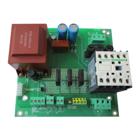
CONTROL SYSTEM
PIC 201A S
TECHNICAL NOTICE
In compliance with the legal provisions of the EU directives:
2014 / 30 / UE, Electromagnetic Compatibility Directive,
2014 / 35 / UE, Low Voltage Directive,
2006 / 42 / EC, Machinery Directive,
2009 /EN 1398 , Dock levelers—Safety requirements
ETME
N.B : The product features can be modified
62, rue Berthie Albrecht
by ETME without notice.
94400 VITRY SUR SEINE
Non-contractual diagrams and pictures.
Tel: 01.46.82.11.00 / Fax: 01.46.82.11.04
Email : Info@ETME.COM
02/11/2017
NOTPIC201AS-T-01
1/8
Publicité
Table des Matières

Sommaire des Matières pour ETME PIC 201A S
- Page 1 CONTROL SYSTEM PIC 201A S TECHNICAL NOTICE In compliance with the legal provisions of the EU directives: 2014 / 30 / UE, Electromagnetic Compatibility Directive, 2014 / 35 / UE, Low Voltage Directive, 2006 / 42 / EC, Machinery Directive, 2009 /EN 1398 , Dock levelers—Safety requirements...
-
Page 2: Important Instructions
The materials employed must be adapted to the weather conditions of the place of installation. The PIC 201A S electronic circuit board must be placed in an enclosure with a protection index higher or equal to IP In case of any doubt about the security and/or reliability regarding the setting up of this product, stop the installation procedure and contact the equipment distributor. -
Page 3: Technical Caracteristics
CIRCUIT BREAKE - ..- ..COMMANDES SIGNAL SAFETY THE ENVIRONMENT OF ETME’S PRODUCT MUST ETME Product BE BROUGHT INTO CONFORMITY WITH ALL EU DIRECTIVES THAT APPLY AND THE APPLICABLE SECTIONS OF THE INSTALLATION STANDARDS Conformity EC IN FORCE ON THE GEOGRAPHICAL AREA OF... -
Page 4: Operating
BOARD LAYOUT AND TERMINAL BLOCKS CONNECTION Fuses Values 500V/6.3AT/HPC 5x20 500V/6.3AT/HPC 5x20 500V/6.3AT/HPC 5x20 250V/1.6 AT 5x20 Terminal blocks and switches description Blocks 1-2 : Door Contact (LS…) Blocks 3-4 : Wheel-Lock Contact DC Valve output. (Blue) Voltage Value selection by SW1 AC Valve output. - Page 5 2009 /EN 1398 , Niveleurs—Exigences de sécurité ETME N.B : les caractéristiques des produits peuvent être 62, rue Berthie Albrecht 94400 VITRY SUR SEINE modifiées par ETME sans préavis. Tel: 01.46.82.11.00 / Fax: 01.46.82.11.04 Schémas et photos non contractuels. Email : Info@ETME.COM 02/11/2017...
-
Page 6: Consignes Importantes
Ce produit a été étudié et construit par la société ETME qui a pris soin de vérifier la conformité de ses caractéristiques avec les contraintes des normes en vigueur. -
Page 7: Caracteristiques Techniques
DISJONCTEUR MAGNETOTHERMIQUE SCHNEIDER TYPE GV2ME (RESPECT DE LA COORDINATION TYPE 1) PROTECTIONS MOTEURS SUIVANT LES PRODUI TS, PROTECTIONS INTERNES OU EXTERNES AU COFFRET ETME. LA CARTE ELECTRONIQUE PIC 201 AS DOIT ÊTRE PLACÉE DANS UN COFFRET IP54 MINIMUM. MOTEURS CARACTERISTIQUES TECHNIQUES Fixation mécanique... -
Page 8: Implantation Et Raccordements
Implantation et raccordements Valeurs des fusibles 500V/6.3AT/HPC 5x20 500V/6.3AT/HPC 5x20 500V/6.3AT/HPC 5x20 250V/1.6 AT 5x20 Descriptions des borniers et des switch Bornes 1-2 : Contact position porte Bornes 3-4 : Contact cale de roue Sortie Electrovanne DC Sélection de la plage de tension (Bleu) avec SW1 Sortie Electrovanne AC...