Table des Matières
Publicité
Les langues disponibles
Les langues disponibles
Liens rapides
Publicité
Table des Matières

Sommaire des Matières pour Alfa Laval AquaPool-7
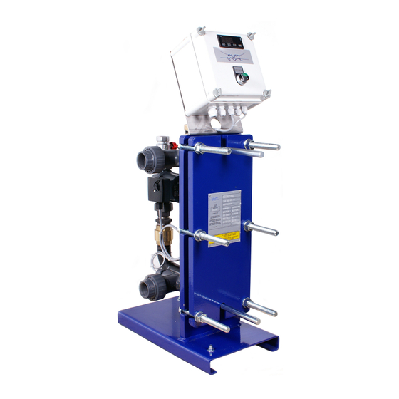
- Page 1 All manuals and user guides at all-guides.com NOTICE D’INSTALLATION, DE MISE EN SERVICE ET D’ENTRETIEN INSTALLATION, COMMISSIONING AND MAINTENANCE MANUAL MODULES PISCINE / SWIMMING POOL HEATERS AquaPool Ver. 3.2 du 7/07/2008...
-
Page 2: Installation Du Module Aquapool
All manuals and user guides at all-guides.com Installation du module AquaPool Install the AquaPool Les modules compacts de réchauffage d’eau de piscine de The swimming pool water heating modules of the la gamme AquaPool sont conçus pour une installation AquaPool range are designed for indoor installation in intérieure en local technique hors gel, sec et suffisamment plant rooms properly ventilated, dry and where the ventilé. -
Page 3: Raccordements Electriques
All manuals and user guides at all-guides.com RACCORDEMENTS HYDRAULIQUES HYDRAULIC CONNECTIONS Raccorder : Pipe : • le primaire en A et B directement sur les vannes • the primary in A and B directly on the isolation valves d’isolement depuis bouteille casse-pression. -
Page 4: Reglage Du Thermostat
PRIMARY SWIM. POOL PRIMARY SWIM. POOL Model m3/h m3/h m3/h m3/h m3/h m3/h AquaPool-7 AquaPool-11 AquaPool-17 AquaPool-23 AquaPool-29 AquaPool-35 AquaPool-41 AquaPool-49 AquaPool-55 10,6 PC : Puissance calorifique : Heating capacity EH : Pression disponible à la pompe / Pump external head available FR : Débit d’eau : Water flow rate... - Page 5 All manuals and user guides at all-guides.com...
- Page 6 All manuals and user guides at all-guides.com...
-
Page 7: Paramètres De Contrôle
All manuals and user guides at all-guides.com INSTRUCTIONS POUR L’INSTALLATION ET L’UTILISATION LTR15 Nous vous remercions de la préférence que vous nous avez accordée en choisissant un produit LAE electronic. Avant d'installer l'appareil, veuillez lire attentivement les instructions qui suivent afin d'en obtenir le maximum en termes de sécurité et de performances. 1. -
Page 8: Description Du Fonctionnement
All manuals and user guides at all-guides.com INSTRUCTIONS POUR L’INSTALLATION ET L’UTILISATION ATTENTION: lorsqu'on change l'échelle d'affichage SCL, on doit ensuite ABSOLUMENT reconfigurer les paramètres relatifs aux températures absolues (SPL, SPH, 1SP) et aux différentielles (1HY, 1PB, OS1). Autotest (3 s) En réglage: erreur de timeout 1 Température sonde T1 En réglage: erreur de timeout 2... -
Page 9: Autoréglage (Autotuning)
All manuals and user guides at all-guides.com INSTRUCTIONS POUR L’INSTALLATION ET L’UTILISATION Overshoot 4.4.2. R . On obtient l’annulation de l’erreur ÉGULATION PROPORTIONNELLE INTÉGRALE en régime en introduisant une action intégrale dans le système de régulation. Le temps de l'action intégrale, 1IT, détermine la vitesse de l'annulation de l’erreur, mais une vitesse élevée (1IT bas) peut être à... -
Page 10: Recalibration
All manuals and user guides at all-guides.com INSTRUCTIONS POUR L’INSTALLATION ET L’UTILISATION de la sonde, diminuer temporairement la consigne en cas de contrôle en chauffage, vice versa en cas de refroidissement, et redémarrer la procédure. Pour éliminer l'indication d’erreur et revenir au mode normal, appuyer sur la touche 5.5. -
Page 11: Schémas De Raccordement
All manuals and user guides at all-guides.com INSTRUCTIONS POUR L’INSTALLATION ET L’UTILISATION SCHÉMAS DE RACCORDEMENT LTR15T1RE-BG LTR15A1RE-BG VIA PADOVA, 25 31046 ODERZO /TV /ITALY TEL. 0422 815320 - 815303 TELEFAX 0422 814073 www.lae-electronic.com LTR15C1FE-BG E-mail: info@lae-electronic.com... - Page 12 All manuals and user guides at all-guides.com INSTRUCTIONS FOR INSTALLATION AND USE. LTR15 Thank you for having chosen a LAE electronic product. Before installing the instrument, please read these instructions carefully to ensure maximum performance and safety. 1. INSTALLATION 1.1. LTR15 is sized 77x35x77 mm (WxHxD). It is inserted into the panel through a hole 71x29 mm and secured by pressing gently into the relative clamps.
-
Page 13: Operation Description
All manuals and user guides at all-guides.com INSTRUCTIONS FOR INSTALLATION AND USE. CAUTION: when changing the display scale SCL, the parameters related to the absolute (SPL, SPH, 1SP) and differential (1HY, 1PB, OS1) temperatures MUST be reconfigured. Internal self-test (3 seconds) In tuning: timeout 1error Sensor T1 temperature In tuning: timeout 2 error... -
Page 14: Auto-Tuning
All manuals and user guides at all-guides.com INSTRUCTIONS FOR INSTALLATION AND USE. Overshoot 4.4.2. P . The steady-state error is cancelled by ROPORTIONAL INTEGRAL CONTROL inserting an integral action into the control system. The integral action time, 1IT, determines the speed of cancellation of the error, but a high speed (1IT low) may be the cause of overshoot and instability in the response. -
Page 15: Serial Communication
All manuals and user guides at all-guides.com INSTRUCTIONS FOR INSTALLATION AND USE. to reduce swings in steady-state temperature, increase the integral action time 1It; system stability is thus increased, although its response speed is decreased; to increase the speed of response to the variations in temperature, increase the derivative action time 1Dt; caution: a high value makes the system sensitive to small variations and may be a source of instability. -
Page 16: Wiring Diagrams
All manuals and user guides at all-guides.com INSTRUCTIONS FOR INSTALLATION AND USE. WIRING DIAGRAMS LTR15T1RE-BG LTR15A1RE-BG VIA PADOVA, 25 31046 ODERZO /TV /ITALY TEL. 0422 815320 - 815303 TELEFAX 0422 814073 www.lae-electronic.com LTR15C1FE-BG E-mail: info@lae-electronic.com...