Publicité
Liens rapides
Die ECD Anzeigeeinheit wird gemeinsam mit den
Controllern der Baureihen EC3 von Emerson
eingesetzt, siehe Tabelle:
Typ
EC3-Controller
EC3-612/611, EC3-622/621, EC3-642/641,
ECD-000
EC3-672/671, EC3-752/751, EC3-812/811,
EC3-922/921
ECD-001 EC3-332/-331
ECD-002 EC3-X33/-X32, EC3-D72/-D73
!
Sicherheitshinweise:
•
Die Anzeigeeinheit kann bei Anschluß an andere
als die oben spezifizierten Controller beschädigt
werden.
•
Halten Sie die Temperaturen innerhalb der
vorgeschriebenen Grenzen.
Technische Daten
Versorgungs
von EC3 über das Anschlußkabel
spannung
Anzeige
2½-stellige, rote LED-Anzeige mit
Dezimalpunkt
LED
bis zu 7 Indikatoren, siehe EC3
Indikatoren
Controller Anleitung
Temperatur
0 ... +60°C (Betrieb),
-20 ... +65°C (Lagerung)
Luftfeuchte 0 ... 80% r.h. nicht kondensierend
Schutzart
IP65 (bei Einbau in Schalttafel mit
Dichtung)
Anschluß-
ECC-N10 (1,0m), ECC-N30 (3,0m)
kabel
ECC-N50 (5,0m) oder CAT5 Kabel mit
RJ45 Steckern
The ECD Display Unit is for use with EC3-Series
controllers from Emerson, see table:
Type
EC3-Controller
EC3-612/611, EC3-622/621, EC3-642/641,
ECD-000
EC3-672/671, EC3-752/751, EC3-812/811,
EC3-922/921
ECD-001 EC3-332/-331
ECD-002 EC3-X33/-X32, EC3-D72/-D73
!
Safety instructions:
Display unit can be damaged, if used with others
•
than the above specified controllers.
Keep the temperatures within the specified
•
limits.
Technical data
Power
From EC3 via connecting cable
supply
Display
2½-digit red LED with decimal point
LED
up to 7 Indicators, see EC3 Controller
Indicators
Instructions
Temperature
0 ... +60°C (operating),
-20 ... +65°C (storage)
Humidity
0 ... 80% r.h. non condensing
Protection
IP65 (front protection with gasket)
class
Connecting
ECC-N10 (1,0m), ECC-N30 (3,0m)
cable
ECC-N50 (5,0m) or CAT5 Cable with
RJ45 Plugs
Marking
ECD__65133__R03.doc
ECD Anzeigeeinheit
Montageanleitung
Montage
Die Anzeigeeinheit ECD kann in Frontplatten mit
einem Ausschnitt von 71 x 29mm montiert werden,
siehe Abmessungen oben.
Anzeigeeinheit vorsichtig mit eingefahrenen Halter-
ungen in den Frontplattenausschnitt einschieben.
Beiliegenden Imbusschlüssel in die Löcher auf der
Frontseite einstecken und im Uhrzeigersinn drehen.
Die Halterungen treten aus dem Gehäuse hervor und
bewegen sich in Richtung Frontplatte.
Imbussschraube weiterdrehen, bis die Halterung die
Frontplatte leicht berührt. Dann auch die zweite
Halterung in diese Position bringen.
Erst jetzt beide Seiten gleichmäßig anziehen, bis die
Anzeige festsitzt. Achtung: Halterung vorsichtig
anziehen, ansonsten droht Bruchgefahr.
ECD Display Unit
Mounting Instructions
Mounting
The ECD-001 can be mounted in panels with a 71 x
29 mm cutout. See dimensional drawing above for
space requirements.
Push controller into panel cutout.
Insert allen key into front panel holes and turn
clockwise. Mounting lugs will turn and gradually
move towards panel.
Turn allen key until mounting lug barely touches
panel. Then move other mounting lug to the same
position.
Tighten both sides very carefully until controller is
secured. Do not over tighten as mounting lugs will
break easily.
replaces Rev.: 01
Verdrahtung
ECD mit EC3 über das Anschlusskabel ECC-Nxx
oder sonstigem Standard CAT5-Kabel mit RJ45
Steckern verbinden.
Anzeige
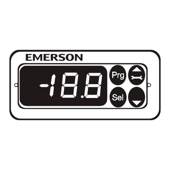
ECD zeigt einen Messwert des angeschlossenen EC3
Controllers permanent an. Mit der SEL-Taste können
temporär andere Messwerte angezeigt werden. Wird
ca 2 Minuten keine Taste betätigt erscheint wieder die
Standardanzeige.
Bei einem Fehler blinkt die Anzeige, Fehlercode und
Messwert
werden
Informationen über die angezeigten Messwerte und
die Fehlercodes sind der Betriebsanleitung des
angeschlossenen Controllers zu entnehmen.
Parametereinstellung
Die Parametereinstellung ist aus Sicherheitsgründen
passwortgeschützt. Die Eingabe des Passwortes und
die Veränderung der Parameter ist in der jeweiligen
EC3 Betriebsanleitung ausführlich beschrieben.
Die Tastenfunktionen können auch mit einer
Infrarotfernbedienung (Option) aktiviert werden.
Abmessungen
Wiring
Use connecting cable ECC-Nxx or any other standard
CAT5-Cable with RJ45 plugs to connect ECD with
EC3.
Display
ECD is showing one measured value of the connected
EC3 controller. Press the SEL button to scroll through
all possible displayable data. After approximately 2
Minutes the display will again display the default
value.
In case of an alarm the display is blinking. The alarm
code and the measured value are displayed
alternatively.
Consult the controllers operating instructions for a
detailed description of all Alarm Codes.
Parameter Setting
The parameter setting is password protected.
Password entry and parameter modification is
described in the respective EC3 controller operating
instructions.
All keys can be alternatively operated with the
(optional) Infrared remote control.
Dimensions
See figure above
1 / 5
D
abwechselnd
angezeigt.
GB
PCN 862 892 01.02.2009
Publicité

Sommaire des Matières pour Emerson ECD Serie
- Page 1 Montageanleitung Die ECD Anzeigeeinheit wird gemeinsam mit den Montage Verdrahtung Controllern der Baureihen EC3 von Emerson Die Anzeigeeinheit ECD kann in Frontplatten mit ECD mit EC3 über das Anschlusskabel ECC-Nxx eingesetzt, siehe Tabelle: einem Ausschnitt von 71 x 29mm montiert werden,...
- Page 2 寸法 寸法 寸法 寸法 サイドを締め付けます。突起部は壊れやすいの で締め過ぎには注意して下さい。 ECD Display Instructiuni de montaj Display-ul ECD se foloseste cu controlerele Emerson Controler EC3 EC3-672/671, EC3-752/751, EC3-812/811, seria EC3, conform tabelului de mai jos: ECD-000 EC3-612/611, EC3-622/621, EC3-642/641, EC3-922/921 ECD__65133__R03.doc replaces Rev.: 02 2 / 5...
- Page 3 ECD-001 EC3-332/-331 Montaj Cablaj ECD-002 EC3-X33/-X32, EC3-D72/-D73 ECD-001 poate fi montat in tablouri cu decupaj 71 x Folositi cablu de conexiune ECC-Nxx sau orice alt 29 mm . Vezi schema cu dimensiuni de mai sus. cablu CAT5 standard cu conexiune RJ45 ptr a Instructiuni de siguranta: conecta ECD cu EC3.
- Page 4 Instructions de montage Le module d'affichage ECD est prévu pour les Montage Câblage régulateurs Emerson série EC3, voir tableau : L'ECD-001 peut être monté en façade dans une Utiliser le câble de connexion ECC-Nxx (ou un autre Type Régulateurs EC3 découpe de 71 x 29 mm.
- Page 5 ECC-N10 (1,0m), ECC-N30 (3,0m) connessione ECC-N50 (5,0m) o cavo CAT5 con spina RJ45 Emerson Electric GmbH & Co OHG - Postfach 1251 - Heerstraße 111 - D-71332 Waiblingen - Deutschland - Tel.: +49-(0)7151-509-0 - Fax +49-(0)7151-509-200 www.emersonclimate.eu ECD__65133__R03.doc replaces Rev.: 02 5 / 5 PCN 862 892 27.07.2009...
