Table des Matières
Publicité
Les langues disponibles
Les langues disponibles
Liens rapides
INSTRUCTION MANUAL
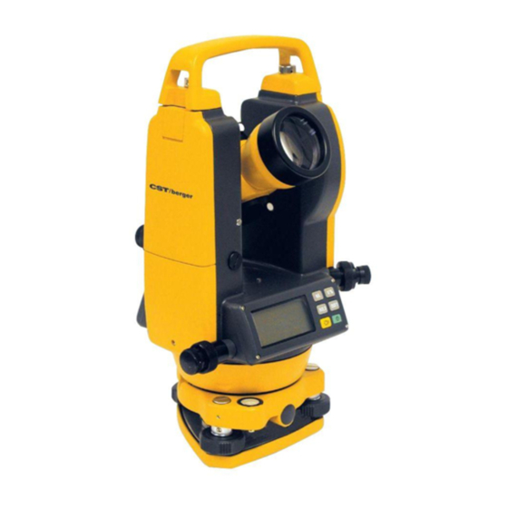
Electronic Digital
Transit/Theodolite
Models
56-DGT2
56-DGT10
I I n n s s t t r r u u c c t t i i o o n n M M a a n n u u a a l l
M M a a n n u u a a l l d d e e I I n n s s t t r r u u c c c c i i o o n n e e s s
M M a a n n u u e e l l d d ' ' I I n n s s t t r r u u c c t t i i o o n n s s
M M a a n n u u a a l l e e d d i i I I s s t t r r u u z z i i o o n n i i
B B e e d d i i e e n n u u n n g g s s a a n n l l e e i i t t u u n n g g
I I n n s s t t r r u u ç ç õ õ e e s s d d e e U U t t i i l l i i z z a a ç ç ã ã o o
Publicité
Table des Matières

Manuels Connexes pour CST/BERGER 56-DGT2

Sommaire des Matières pour CST/BERGER 56-DGT2
- Page 1 M M a a n n u u a a l l d d e e I I n n s s t t r r u u c c c c i i o o n n e e s s 56-DGT2 M M a a n n u u e e l l d d ’...
- Page 2 FIG. 1 2 • DGT2 - DGT10...
- Page 3 FIG. 2 FIG. 3 FIG. 4 FIG. 5 FIG. 6 FIG. 7 DGT2 - DGT10 • 3...
- Page 4 FIG. 8 FIG. 9 FIG. 11 FIG. 10 V -8.8.8.8.8.8.8. FIG. 12 HOLD OSET 8.8.8.8.8.8.8. FIG. 13 HOLD OSET 0.0.0.0.0.0.0. 9 0 0 0 0 0 FIG. 14 HOLD OSET 0 0 0 0 0 4 • DGT2 - DGT10...
- Page 5 FIG. 15 Full Partial Power Power Power Power FIG. 16 FIG. 17 FIG. 18 FIG. 19 FIG. 20 DGT2 - DGT10 • 5...
- Page 6 56-DGT10 5 Sec. Electronic Digital Transit/Theodolite Copyright© 2005-2006 CST/Berger. All rights reserved The information contained herein is proprietary information of CST/Berger, and is subject to change without notice. This document shall not be copied or otherwise reproduced without CST/Berger's written consent.
-
Page 7: Functions
the faces toward each other. Position and level the instrument so that the distance from the instrument to each rod is the same (measure; Fig. 2). Take a reading on each rod with the instrument (or mark each piece of strapping where the crosshair is sighted). -
Page 8: Operating Keys
Operating Keys FUNCTION OPERATION SYMBOL Used to switch horizontal angle between clockwise Setting horizontal rotation (HR) and counterclockwise rotation (H L). angle rotational The direction changes each time the button direction is pressed. Used to lock current horizontal angle into display. The horizontal angle reading will flash when this button Locking horizontal HOLD... - Page 9 Setting Up Your Measurement Preferences A) Turn the power on B) Press “R/L” and “V%” at the same time. A tone will be heard and the display should look similar to what’s shown at right. C) To specify your measurement preferences: PRESS DISPLAY Change the readout of the horizontal...
- Page 10 Once all preferences have been input, press the “H/R” and “V%” at the same time. A long tone will be heard and the display will return to normal. 10 • DGT2 - DGT10...
-
Page 11: Preparation For Measurement
PREPARATION FOR MEASUREMENT Mounting And Leveling Mount and level the instrument carefully to get the best performance. 1. Place the tripod over the ground datum point and tighten the legs. 2. Attach the instrument to the tripod and tighten snugly (Follow Step 3 for the DGT10 only) 3. - Page 12 seeing the target shift with respect to the crosshairs. 3. If there is parallax, readjust the eyepiece. Always remove any parallax before operation to assure accurate measurements. Aiming At The Target Loosen the clamps and point at the target using the targeting sights located above and below the telescope.
- Page 13 Presetting Horizontal Angles 1. Turn the instrument until the desired horizontal angle is shown on the display. HR 60°00’00" 2. Press the “HOLD” button. HR 60°00'00" will blink on and off. 3. Aim the instrument at the target and press the “HOLD” button again. The horizontal angle will be released from that point.
-
Page 14: Checks And Adjustments
HANDLING OF POWER SUPPLY Removing The Battery Compartment Push down on the battery compartment latch and pull the top of the battery compartment away from the instrument. (Fig .21) Replacing Batteries 1. Push down on the hook to remove the metal battery door. (Fig .22) 2. - Page 15 C) Return to the original position in step A. Recheck the bubble and center as necessary. Rotate the instrument 180° (200g). The bubble should still be centered in the vial. If not, go to step D. D) Using the adjusting pin provided in the case, turn the screw until the bubble moves halfway back to its original position.
- Page 16 D) Using the adjusting pin provided in the case, turn the reticle adjusting screws until half the displacement has been removed. Loosen one screw 1/4 turn, then tighten the opposing screw 1/4 turn. E) Repeat steps A through D until there is no displacement of the target when the instrument is turned about its vertical axis.
-
Page 17: Accessories
TRIBRACH (FOR DGT10 ONLY) Removal: Turn the locking lever 180° counterclockwise (FIG. 28). The instrument can now be removed from the tribrach. Attachment: Line up the tongue on the instrument with the notch in the tribrach (FIG. 29). Turn the locking lever 180°... -
Page 18: Environmental Protection
Do not throw used batteries into waste, fire or water but dispose of in an environmentally friendly manner according to the applicable legal regulations. SPECIFICATIONS Description 56-DGT2 56-DGT10 Telescope Overall Length 155mm (6.1") 155mm (6.1") - Page 19 Repair or replacement under this Warranty does not affect the expiry date of the Warranty. To the extent permitted by law, CST/Berger shall not be liable under this Warranty for indirect or consequential loss resulting from deficiencies in this product.
- Page 20 Base nivelante Nivel esférico (sólo DGT-10) CALIBRACIÓN La precisión del teodolito CST/Berger ha sido comprobada antes de su salida de la fábrica. El instrumento ha sido embalado adecuadamente para protegerlo de las incidencias del transporte. Sin embargo durante el transporte puede ser manjado sin cuidado. Para evitar el uso del instrumento descorregido se aconseja comprobarlo antes de su utilización.
-
Page 21: Funcionamiento Del Equipo
B-B´). En caso contrario el valor obtenido es el error del equipo a 60m. La corrección y calibración del equipo debe de hacerlo personal técnico adecuado. Se aconseja enviar el equipo a un servicio técnico de CST/Berger. Aconsejamos realizar esta verificación periodicamente para garantizar la precisión de las medidas del instrumento. -
Page 22: Explicación De Las Teclas
Explicación de las teclas SÍMBOLO DE FUNCIÓN EXPLICACIÓN LA TECLA Dirección del sentido de los Cada vez que se presiona esta tecla se ángulos cambia el sentido del ángulo hori zontal. Sirve para colocar el ángulo horizontal que se quiere. La lectura del ángulo horizontal Fijación de un ángulo horizontal parpadea cuando se presiona esta tecla. - Page 23 AJUSTES A) Encender la unidad B) Presionar “R/L” y “V%” al mismo tiempo. Se escuchará un tono de audio y el display se mostrará como en la figura a la derecha. C) Para configurar el equipo: PRESIONAR PARA PANTALLA cambiar entre 10 o 20 segundos la resolución de lectura de los ángulos horizontales y verticales (si está...
-
Page 24: Ajuste Inicial
Opción Ub, cero en posición horizontal Opción Ua, cero en posición cenital Opción Uc, ángulo de elevación Una vez impuestas las opciones deseadas, presionar de nuevo “H/R” y “V%” en el mismo tiempo. Se escuchará un tono largo y el display volverá normal. AJUSTE INICIAL Estacionamiento y nivelación Un buen ajuste inicial es muy importante para el correcto funcionamiento del instrumento. - Page 25 Montar el teodolito en el trípode (leer el paso 3 para el DGT10) En el DGT10, utilizar la burbuja esférica para nivelar aproximadamente el instrumento. A A ) ) Utilizar los tornillos de ajuste “ “ A A ” ” y “ “ B B ” ” para centrar la burbuja esférica de la izquierda a la derecha (Fig.
-
Page 26: Encendido Del Instrumento
Apuntar y medir a un objeto Localice primero con el punto de mira el objeto a medir, luego enfoque con el objetivo el punto a medir (Fig. 11). MEDICIONES Encendido del instrumento Encender el instrumento. Todos los segmentos de la pantalla estarán encendidos para dos segundos (Fig. -
Page 27: Códigos De Errores
Medición de ángulos verticales Se puede seleccionar entre tres posibles esquemas, cuando se quiera medir ángulos verticales. Las tres selecciones son: Ua, Ub y UC (ver esquemas en el capitulo “Ajustes”). Medición en porcentaje (Fig. 17) Presionando la tecla “V%”, se puede visualizar el ángulo vertical en grados o en porcentaje, entre 0% y 100%. -
Page 28: Inserción / Cambio De Las Pilas
INSERCIÓN / CAMBIO DE LAS PILAS Quitar el bloqueo del compartimiento de las baterías y sacar del instrumento las mismas (Fig. 21). Bajar el gancho para retirar la tapa metálica del alojamiento de las pilas (Fig. 22). Introducir las pilas según la adecuada polarización y volver a colocar la tapa metálica (Fig. 23). - Page 29 D) Utilizando la llave de ajuste que se Desplazamiento encuentra en el maletín, girar el tornillo hasta que la burbuja se Mitad del mueva la mitad del error hacia desplazamiento atrás con respecto a su posición original. E) Repetir los pasos A-C, hasta que la burbuja permanezca centrada, independientemente de la rotación del instrumento.
- Page 30 D) Usando la llave incluida en la caja de transporte, desplazar el retículo de la plomada la mitad del error que exista Desplazamiento respeto a la señal. Girar de modo contrapuesto los Mitad del desplazamiento tornillos tal y como se indica en la figura (si se afloja 1⁄4 de vuelta uno, apretar 1⁄4 de vuelta el opuesto)
- Page 31 BASE NIVELANTE (SÓLO PARA EL DGT-10) S S e e p p a a r r a a r r : : Girar el tornillo de bloqueo 180º (Fig. 28). El instrumento podrá ser separado de la base. F F i i j j a a c c i i ó ó n n : : Insertar el instrumento y buscar la posición haciendo coincidir la muescas de la base con los topes que se encuentran bajo el instrumento (Fig.
-
Page 32: Datos Técnicos
DATOS TÉCNICOS DescripciÓn 56-DGT2 56-DGT10 A A n n t t e e o o j j o o Longitud 155 mm (6.1”) 155 mm (6.1”) Apertura efectiva 45 mm (1.77”) 45 mm (1.77”) Aumentos Imagen Derecha Derecha Campo de visión 1°30’... - Page 33 Cualquier reparación o reemplazo durante la vigencia de esta Garantía no afecta a su fecha de vencimiento. Dentro de lo autorizado por la legislación vigente, CST/Berger no se obliga por esta Garantía a compensar pérdidas como resultado de deficiencias en el producto.
-
Page 34: Description Du Théodolite (Fig. 1)
56-DGT10 Théodolite électronique numérique 5’’ Copyright© 2002-2003 CST/Berger. Tous droits réservés. Les informations contenues dans le présent manuel appartiennent à CST/Berger qui se réserve le droit d’apporter toute modification technique sans préavis. Interdiction de copier ou de reproduire le présent manuel sans avoir obtenu auparavant l’autorisation écrite de CST/Berger. -
Page 35: Description Du Panneau De Contrôle
Placer deux mires à chaque extrémité de cette surface en s’assurant qu’elles soient positionnées face à face. Mettre l’instrument à niveau de telle façon que la distance entre l’instrument et chacune des mires soit la même (mesure; fig. 2). Faire un relevé sur chacune des mires avec l’instrument. Noter la différence. Puis, déplacer l’instrument à... -
Page 36: Fonctions Des Touches
Fonctions des Touches SYMBOLES FONCTION UTILISATION Bouton servant à A utiliser pour choisir le sens de l’angle Hz – Hr = sens es sélectionner le sens aiguilles d’une montre. Hl = sens inverse. de l’angle Hz A utiliser pout mémoriser la valeur de l’angle Hz. La mesure Bouton servant à... -
Page 37: Configuration De L'appareil
Configuration de l’appareil Mettre le théodolite en marche en appuyant sur la touche. Appuyer alors simultanément sur le touches R/L et V%. Vous entendrez un son et l’écran devrait être pareil à ce qui est indiqué à droite. Choisissez alors de quelle manière vous voulez travailler. TOUCHE FONCTION ÉCRAN... - Page 38 Mode Ub, angle vertical Mode Ua, angle zénithal Mode Uc, angle de hauteur Appuyer une nouvelle simultanément sur les touches H/R et V% pour enregistrer votre configuration (un signal sonore prolongé retentira). 38 • DGT2 - DGT10...
-
Page 39: Preparation A La Mesure
PREPARATION A LA MESURE Mise en station de l’instrument Installez le théodolite de manière la plus correcte possible pour obtenir de bons résultats. Positionner le trépied sur le point de repère. Fixer l’appareil sur le trépied et visser à fond la vis de blocage (Pour le nivellement du théodolite DGT10, suivre la description du point 3). -
Page 40: Prises De Mesures
Faites la mise au point de la lunette en visant un objet. En bougeant lentement les yeux de haut en bas et de gauche à droite, le réticule doit rester fixe par rapport à l'objet visé. Si vous avez toujours un problème d’erreur de parallaxe, affinez le réglage du réticule avec l'oculaire. -
Page 41: Mesure Des Angles Verticaux
Présélection de l’angle horizontal Tourner le théodolite jusqu’à ce que l’angle horizontal soit affiché sur l’écran, par exemple HR60°00’00”. Appuyer sur le bouton HOLD. HR60°00’00” clignote. Pointer l’appareil vers la cible et appuyer de nouveau sur le bouton HOLD. L’angle HR60°00’00” sera le point de départ de la mesure des angles Hz. -
Page 42: Remplacement Du Pack Batterie
Après le étallonage, contrôler toujours la précision de l’appareil. Il est conseillé de limiter les contrôles à ceux qui sont indiqués dans ce chapitre. Pour les réparations de nature différente, s’adresser à un service après-vente agréé CST/Berger. Vérification et ajustement Nivelle horizontale A) Orienter l’appareil de manière à... - Page 43 C) Remettre l’appareil à la position du point A. Contrôler à nouveau la bulle et la centrer s’il y a lieu. Faire tourner l’appareil de 180° (200 g). la bulle doit rester centrée; dans le cas contraire, passer au point D. Déplacement D) A l’aide de la clavette livrée dans la mallette, intervenir sur la vis jusqu’à...
- Page 44 D) A l’aide du pointeau de réglage faisant partie de l’équipement, intervenir sur les vis de calibrage de manière à Déplacement compenser la moitié de l’erreur de pointage. Tourner de 1/2 du déplacement manière opposée les vis indiquées sur la figure (si l’on dévisse une vis de 1⁄4 de tour, visser l’autre de 1⁄4 de tour).
- Page 45 EMBASE (SEULEMENT DGT10) Le théodolite possède une embase plomb optique amovible. Pour détacher l’embase faites tourner la molette dans le sens inverse des aiguilles d’une montre (Fig. 28). Pour le fixer, faites tourner la molette de 180° dans le sense des aiguilles d’une montre (Fig. 29). ACCESSORIES E E q q u u i i p p e e m m e e n n t t S S t t a a n n d d a a r r d d : : coffret rigide, protège pluie, set d’accessories de réglage, fil à...
-
Page 46: Protection Environnementale
Ne jetez pas les piles dans la poubelle de la maison, le feu ou l’eau, mais débarrassez-vous en d’une manière respectueuse de l’environnement selon les règlements légaux applicables. DONNÉES TECHNIQUES Modele 56-DGT2 56-DGT10 L L U U N N E E T T T T E E Longueur 155 mm (6.1 po) -
Page 47: Garantie
1641 et suivants du Code Civil relatifs à la garantie légale des vices cachés. Les produits de mesure et niveaux électroniques CST/berger sont garantis un an contre tout vice de fabrication à compter de leur date d’achat par l’utilisateur final auprès d’un revendeur CST/berger. - Page 48 Toute intervention sur les produits, autre que celle effectuée dans le cadre normale de l’utilisation de ces produits ou par le Service Après vente CST/berger, entraîne la nullité de la garantie. De même, le non respect des informations contenues dans le mode d’emploi entraîne de fait la suppression de la garantie.
- Page 49 5 sec. Teodolite elettronico digitale Copyright© 2002-2003 CST/Berger. Tutti i diritti riservati. Le informazioni contenute in questo manuale sono di proprietà della CST/Berger e sono soggette a modifiche senza obbligo di preavviso. Questo documento non può essere riprodotto in tutto o in parte senza l’autorizzazione scritta della CST/Berger.
- Page 50 B – B’). In caso contrario, il valore ottenuto è l’errore strumentale a 60 metri. La calibrazione del teodolite deve essere effettuata da personale esperto. Vi consigliamo di rivolgervi ad un centro assistenza CST/Berger. Per la vostra sicurezza, vi consigliamo di effettuare verifiche periodiche del vostro teodolite.
-
Page 51: Funzione Dei Tasti
Funzione dei tasti SIMBOLI DEI TASTI FUNZIONI OPERAZIONI Ogni volta che si preme il tasto si cambia Direzione della lettura la direzione di lettura dell’angolo dell’angolo orizzontale orizzontale tra orario (Hr) e antiorario (Hl). Blocca l’angolo orizzontale visualizzato. La rotazione dello strumento non Blocca la lettura provoca la modifica dell’angolo. - Page 52 Impostazioni A) Accendete lo strumento. B) Premete contemporaneamente i tasti “R/L” e “V%”. Sentirete un segnale acustico ed il display mostrerà i simboli riportati nella figura a fianco C) Fate riferimento alla tabella seguente per le varie impostazioni. PREMERE DISPLAY Cambiare la risoluzione del display.
- Page 53 Modo Ua, angolo zenitale Modo Ub, angolo verticale Modo Uc, angolo d’elevazione Terminata la fase di impostazione delle preferenze di funzionamento, premete di nuovo i tasti “H/R” e “V%” allo stesso tempo. Un segnale acustico prolungato vi avviserà che le modifiche sono state memorizzate.
-
Page 54: Messa A Fuoco
PREPARAZIONE ALLA MISURA Montaggio e Livellamento Montate e livellate lo strumento con la massima cura per ottenere le migliori prestazioni possibili. Posizionate il treppiede sul punto di riferimento. Fissate lo strumento sul treppiede ed avvitate a fondo la vite di blocco. (Per livellare il Teodolite DGT10 seguite il punto 3.) Nel DGT10 livellate innanzitutto la livella circolare. - Page 55 Per evitare questi errori, seguite le seguenti raccomandazioni: Mettete a fuoco il bersaglio. Muovete l’occhio lentamente in tutte le direzioni. Il reticolo non deve spostarsi dal bersaglio. In caso contrario, ripetete la messa a fuoco con maggior cura. E’ molto importante verificare l’allineamento del reticolo sul bersaglio per fare misure d’alta precisione.
- Page 56 Preselezione di un Angolo Orizzontal Ruotate lo strumento finché il display non mostra l’angolo da impostare. Premete il tasto HOLD. L’angolo orizzontale visualizzato sarà bloccato. Puntate il bersaglio e premete di nuovo il tasto HOLD. L’angolo orizzontale sarà sbloccato e le letture angolari partiranno dal collimato, in funzione dell’angolo impostato.
-
Page 57: Sostituzione Delle Batterie
SOSTITUZIONE DELLE BATTERIE R R i i m m o o z z i i o o n n e e d d e e l l P P o o r r t t a a B B a a t t t t e e r r i i e e Per rimuovere il porta batterie, spingete verso il basso il tasto di sblocco del coperchio (Fig. - Page 58 Ruotate lo strumento di 180° (200g). Spostamento La bolla deve rimanere centrata; in caso contrario passate al punto D. Metà dello D) Usando la chiavetta fornita nella spostamento valigia, agite sulla vite fino a che la bolla non si sposta indietro della metà...
- Page 59 D) Usando lo spillo di regolazione che è in dotazione allo strumento, agite sulle viti di calibrazione fino a compensare la metà Spostamento dell’errore di puntamento. Ruotate in modo contrapposto Metà dello spostamento le viti indicate in figura (se svitate una vite di 1⁄4 di giro, avvitate l’altra di 1⁄4 di giro) E) Ripetete la verifica descritta ai punti ( A –...
-
Page 60: Cura E Manutenzione
TRICUSPIDE (SOLO DGT10) R R i i m m o o z z i i o o n n e e : : Girate la levetta di bloccaggio di 180° in senso antiorario. Lo strumento può essere rimosso dal tricuspide. (Fig. 28) F F i i s s s s a a g g g g i i o o : : Inserite i piedini posti sotto lo strumento nei fori presenti sulla tricuspide e girate di 180°... -
Page 61: Caratteristiche Tecniche
CARATTERISTICHE TECNICHE Descrizione 56-DGT2 56-DGT10 C C A A N N N N O O C C C C H H I I A A L L E E Lunghezza... - Page 62 CST/Berger a division of Stanley Works, garantisce questo prodotto riguardo a difetti nei materiali o della manodopera per un anno dalla data d’acquisto. I prodotti difettosi saranno riparati o sostituiti, a discrezione di CST/Berger, se inviati assieme alla prova d’acquisto.
- Page 63 5 sec elektronischer Digital-Theodolit Copyright © 2002-2003 CST/Berger. Alle Rechte vorbehalten Bei den hier enthaltenen Informationen handelt es sich um geistiges Eigentum von CST/Berger und darf nicht von Dritten ohne ausdrückliche Erlaubnis abgeändert werden. Zur Vervielfältigung ist eine schriftliche Einverständniserklärung von CST/Berger nötig.
- Page 64 Sie 2 gleiche Nivellierlatten im Abstand von 60 m. Positionieren Sie das Gerät etwa in der Mitte der beiden Nivellierlatten. (Abb. 2) Lesen Sie die Werte ab und notieren Sie sie. Platzieren Sie nun das Instrument an einer anderen Stelle in der Verbindungslinie A-B, wie in Abb. 3 beschrieben. Nivellieren Sie das Gerät und lesen Sie die Werte ab.
- Page 65 Bedientasten TASTATUR BEDEUTUNG ANLEITUNG Aktuelle Zählrichtung wird im Anzeigefeld durch Auswahl der Zählrichtung „R“ für rechts und „L“ für links angezeigt. Die des Horizontalkreises Richtung wird durch Drücken der Taste geändert Bei einmaligem Druck wird der aktuelle Wert im Display festgestellt. Die Winkelanzeige blinkt. Das Feststellung der HOLD Instrument kann in die gewünschte Richtung...
- Page 66 Geräte-Konfiguration A) Gerät einschalten B) Drücken Sie die R/L und V% Taste zur gleichen Zeit, dann wird im Display nebenstehende Anzeige erscheinen. C) Änderung der Messeeinstellung DRÜCKEN SIE ANZEIGE Ändert die Anzeige von 10” auf 5”. Die Genauigkeit des Instruments ist 10 Sek und wird dadurch nicht geändert.
- Page 67 Ub-Modus, Vertikalwinkel Ua-Modus, Zenitwinkel Uc-Modus, Höhenwinkel V V e e r r t t i i k k a a l l - - K K r r e e i i s s e e i i n n s s t t e e l l l l u u n n g g Sobald Sie alle Einstellungen eingegeben haben, drücken Sie gleichzeitig auf “H/R”...
-
Page 68: Vorbereitungen Zur Messung
VORBEREITUNGEN ZUR MESSUNG Befestigung und Nivellierung Um eine optimale Anwendung zu gewährleisten sollten Sie das Instrument mit größter Sorgfalt auf dem Stativ befestigen und nivellieren. 1 1 . . Platzieren Sie das Stativ über dem Messpunkt und fixieren Sie die Klemmung 2 2 . -
Page 69: Stromversorgung
Zielausrichtung G G r r o o b b a a u u s s r r i i c c h h t t u u n n g g Lösen Sie die Horizontal-Klammer (Arretierschraube) und zielen Sie mit dem Grobvisier (ober- und unterhalb des Teleskops) auf Ihr Ziel (Abb. -
Page 70: Fehleranzeigen
Messung vertikaler Winkel Es gibt drei verschiedene Anzeigemöglichkeiten zur Auswahl bei der Messung vertikaler Winkel. Beachten Sie dazu Abschnitt „Geräte-Konfiguration“. Messung von Neigungen in Prozent (Abb.17) Durch Drücken von „V%“ können Sie zwischen Neigungsanzeige in Grad zur Anzeige in Prozent (0% bis 100%) wechseln. - Page 71 BATTERIEWECHSEL Ö Ö f f f f n n e e n n d d e e s s B B a a t t t t e e r r i i e e f f a a c c h h s s Drücken Sie die Lasche des Batteriefachdeckels nach unten und nehmen Sie den Deckel nach oben weg.
- Page 72 C) Kehren Sie zur ursprünglichen Stellung aus Punkt a. zurück. Überprüfen Sie die Blase wenn nötig erneut. Drehen Sie das Instrument um 180° (200g). Die Blase sollte sich immer noch im Zentrum der Libelle befinden. Wenn nicht, wiederholen Sie bitte die Schritte ab Schritt D. Abweichung D) Verwenden Sie die beigelegte Einstell-Nadel, drehen Sie die...
- Page 73 C) Entfernen Sie die Einstellschrauben-Abdeckung vom optischen Lot durch Drehen gegen den Abweichung Uhrzeigersinn. Vier Okular- Einstellschrauben werden 1/2 Abweichung freigelegt. D) Verwenden Sie die beigelegte Einstell-Nadel, drehen Sie die Okular- Einstellsschraube bis sich das Fadenkreuz mit dem Justieren Sie das Ziel deckt.
-
Page 74: Wartung Und Pflege
DREIFUß (NUR DGT10) E E n n t t f f e e r r n n e e n n Drehen Sie die Feststell-Hebel um 180° gegen den Uhrzeigersinn. (Abb. 28) Das Instrument kann nun vom Dreifuß abgenommen werden A A n n b b r r i i n n g g e e n n Setzen Sie das Gerät so auf, dass die Erhebung an der Instrumentenunterseite in die Vertiefung des Dreifusses einrastet (Abb. -
Page 75: Umweltschutz
UMWELTSCHUTZ Recyceln Sie die verschiedenen Materialien wenn möglich einzeln, statt Sie in den Müll zu werfen. Gerät, Zubehör und Verpackung sollten umweltfreundlich entsorgt werden. Werfen Sie gebrauchte Batterien niemals in den Müll, ins Feuer oder ins Wasser sondern entsorgen Sie sie auf umweltfreundliche Weise entsprechend den gesetzlichen Bestimmungen. TECHNISCHE DATEN Beschreibung 56-DGT10... - Page 76 Jahr beginnend am Tag des Kaufes für Materialfehler oder Fehler in der technischen Ausführung. Produkte, die in einem dieser Bereiche fehlerhaft sind, werden nach CST/Berger Wahl repariert oder ersetzt [und auf Kosten von CST/Berger], wenn sie zusammen mit dem Kaufbeleg geschickt werden.
- Page 77 Teodolito electrónico digital 5 seg. Copyright© 2002-2003 CST/Berger. Todos os direitos reservados A informação contida neste manual é informação de propriedade da CST/Berger, e está sujeita a alteração sem aviso prévio. Este documento não poderá ser copiado ou em qualquer caso reproduzido sem o consentimento escrito da CST/Berger.
- Page 78 Instale o aparelho numa área o mais nivelada possível e com um comprimento de aproximadamente 66 metros. Coloque duas miras (ou duas réguas) a cerca de 60 metros uma da outra. Instale o aparelho a meia distância de cada uma das miras (Fig. 2). Faça a leitura em cada uma das miras (ou marque nas réguas o ponto da mirada).
- Page 79 Teclado SIMBOLO FUNÇÃO OPERAÇÃO Direcção do sentido da Cada vez que se pressiona esta tecla, o sentido do leitura dos ângulos ângulo horizontal muda horizontais Serve para fixar o ângulo que se deseje. A leitura do ângulo horizontal pisca quando se pressiona esta tecla. Fixação do valor de um HOLD Orienta-se então o aparelho para a estação ou mirada...
- Page 80 AJUSTES A) Ligar o instrumento. B) Pressionar “R/L” e “V%” simultaneamente. ouvir-se-á um pequeno som e o mostrador apresentar-se-á como na figura a la direita. C) Para especificar as medidas pretendidas: PRESSIONAR DISPLAY Pressionando esta tecla durante 10 a 20 segundos altera-se a resolução da leitura dos ângulos horizontais e verticais de grados para graus e 5 a 10 segundos para...
- Page 81 Modo Ua, ângulo do zénite Modo Ub, ângulo vertical Modo Uc, ângulo alto Uma vez impostos os ajustes desejados, pressionar simultaneamente a tecla “H/R” e “V%”. Escutar-se-á um som longo e o mostrador volta ao normal. DGT2 - DGT10 • 81...
- Page 82 PREPARAÇÃO PARA TRABALHO Montagem e nivelamento Um bom ajuste inicial é muito importante para o correcto funcionamento do instrumento. Colocar o tripé sobre o ponto de referência, no solo e bloquear as pernas. Montar o teodolito no tripé (Ler o passo 3 para o DGT10). No DGT10, utilizar a bolha de nível esférica para aproximar o aparelho do nível.
- Page 83 Se produz paralaxe, reajustar a mira. Eliminar sempre qualquer erro de paralaxe antes de usar o instrumento, para assegurar uma medição precisa. Apontar a um Alvo Afrouxar os parafusos de fixação e apontar, através do ponto de mira colocado sobre o telescópio. Deixar algum espaço entre o olho e o ponto de mira (Fig.
- Page 84 instrumento começa a medir o ângulo horizontal a partir deste ponto e do valor Hr 60º 00’ 00”. Medição de Ângulos Verticais Existem três diferentes valores de medida para a medição de ângulos verticais. Vêr os três diferentes valores en el capítulo “Ajustes”. Escolher o modo de ângulo vertical desejado. Medição em Percentagem (Fig 17) Pressionando a tecla “V%”, pode-se visualizar a medição do ângulo vertical em graus ou percentagem, que mede de 0 –...
-
Page 85: Substituição Das Baterias
Depois dos ajustamentos, verifique sempre uma outra vez o equipamento. Nota: Se verificar que o instrumento tem outros desajustes que não os referidos, contacte um Centro de Serviço Autorizado da CST/Berger. Verificação e Calibração Prato do nível de bolha tubolar A) Colocar o nível tubolar paralelo ao alinhamento dos parafusos de nivelamento A e B. - Page 86 B) Girar o aparelho em 90º e centrar Espaço novamente a bolha do nível tubolar com o parafuso C Medio espaço (Fig. 27). C) Reponha o aparelho na posição do primeiro parágrafo. Verifique a bolha e centre-a se necessário. Rode o aparelho em 180º...
- Page 87 óptico. Gire-o no sentido anti- horário. Aparecem então quatro parafusos de ajuste da retícula. Espaço D) Com o pino que acompanha o aparelho, na mala, girar os Medio espaço parafusos de ajustes referidos até que metade do desvio tenha sido corrigido. Desapertar 1⁄4 de um parafuso e apertar 1⁄4 do parafuso oposto.
- Page 88 BASE “TRIBRACH” (SÓ PARA O DGT 10) R R e e m m o o ç ç ã ã o o : Gira em 180º no sentido anti-horário, a alavanca do trinco. O aparelho pode agora ser removido da base (Fig. 28). M M o o n n t t a a g g e e m m : Alinhar o trinco na vertical.
-
Page 89: Protecção Ambiental
Não deite as pilhas usadas para o lixo, fogo ou água; dê-lhes um fim não prejudicial ao ambiente, de acordo com as regulamentações aplicáveis. ESPECIFICAÇÕES Descrição 56-DGT2 56-DGT10 T T E E L L E E S S C C Ó Ó P P I I O O Comprimento... - Page 90 Até ao limite permitido pela lei, a CST/Berger não será responsabilizada por esta Garantia por consequencias diretas ou indiretas em resultado das deficiencias deste produto. Nada nesta garantia deve limitar os direitos da CST/Berger sobre os compradores no cabo de 1) Morte ou acidentes pessoais causados pela sua negligencia ou 2) mau comprtamento intencional ou grave negligencia.
- Page 91 FIG. 23 FIG. 22 FIG. 21 FIG. 25 FIG. 24 FIG. 26 FIG. 27 FIG. 28 FIG. 29 DGT2 - DGT10 • 91...
- Page 92 Z94-DGT10-7 REV.2 (1106)