
Sommaire des Matières pour M-WAVE 640090
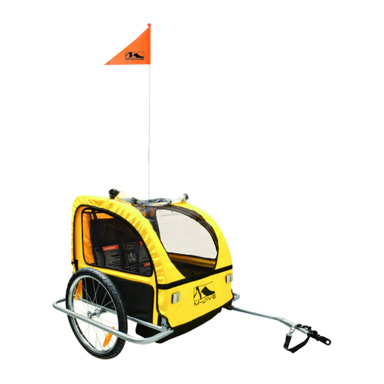
- Page 1 FAHRRADANHÄNGER/ JOGGER Modell 640090 mit Stahlrahmen Modell 640091 mit Alurahmen Modell 640092 mit Alurahmen Modell 640046 mit Stahlrahmen www.m-wave.messingschlager.com...
- Page 2 BEDIENUNGSANLEITUNG & SICHERHEITSHANDBUCH Benutzerhinweise Aufbau des Hauptrahmens Anbau der Laufräder Parken des Anhängers Einbau von Querstange und Sitz Benutzung des 5-Punkt-Gurts Anbringen der Regenhaube Anbringen der Fahne Anbau der Deichsel Anhängen ans Fahrrad BITTE LESEN SIE DIE GANZE ANLEITUNG UND DIE HINWEISE ZUSAMMENBAU...
- Page 3 BENUTZERHINWEISE Radfahren und Radtouren werden immer beliebter. Ihr schöner neuer Anhänger wurde designed, um einen praktischen, komfortablen und stabilen Beitrag zu Ihrer Freizeitausrüstung zu bieten. BITTE LESEN SIE DIE ANLEITUNG VOR AUFBAU UND BENUTZUNG AUFMERKSAM DURCH UND BEACHTEN SIE DIE WARNHINWEISE! W I C H T I G ! PASSAGIERE UND FAHRER SOLLTEN IMMER PASSENDE, GEPRÜFTE UND FUNKTIONIERENDE RADFAHRHELME TRAGEN!
- Page 4 Gepäckabteil Max. Zuladungsgewicht der Kinder: Art. 640046: Gesamtgewicht max. bis 15 kg Art. 640090-92: Gesamtgewicht max. bis 18 kg Maximales Gesamtgewicht Art. 640046: Gesamtgewicht max. bis 47,2 kg (Eigengewicht 15kg zzgl. Zuladung max. 32,2 kg) ...
- Page 5 Den Anhänger nicht überladen! Zulässige Zuladungsgewicht Art. 640046 32,2kg (max. 2 Kinder mit insgesamt max. 30kg + 2,2kg Gepäck) Zulässige Zuladungsgewicht Art. 640090-92 20,2kg (max. 2 Kinder mit insgesamt max. 18kg + 2,2kg Gepäck) Wenn möglich das Hauptgewicht mittig und möglichst weit unten laden, zusätzliches Gepäck nach hinten.
- Page 6 Gehen Sie nie davon aus, dass Sie Vorfahrt haben. Vorsicht beim Einschätzen der Reaktionen von Autofahrern! Nicht auf Hauptverkehrsstraßen, vielbefahrenen Straßen und im unwegsamen Gelände fahren! Nachts möglichst nicht fahren, wenn Kinder im Anhänger sind! Grundsätzlich nachts reflektierende Kleidung tragen und auf eine funktionierende vorschriftsmäßige Beleuchtung achten! ...
- Page 7 TEILELISTE UND EXPLOSIONSZEICHNUNG (Art. 640090 / 640091 / 640092)
- Page 8 NUMMER NAME MENGE NUMMER NAME MENGE Grundrohr Reflektor Seitenrahmen Speichenreflektor * 15 Querrohr 12” Rad * 16 20” Rad Gabel Radschutz Sicherheitsflagge Sicherungsstift Sicherungsstift Zugstange Entriegelungsknopf * 20 Kupplung Knopf * 21 Stoffboden Handbremse * 22 Seitenwand Bügel * 23 Stoffsitz Haltegurt *...
- Page 9 TEILELISTE UND EXPLOSIONSZEICHNUNG (Art. 640046)
- Page 10 NUMMER NAME MENGE NUMMER NAME MENGE * 13 Grundrohr Halteband Seitenrahmen Stoffboden Querrohr Seitenwand Zugarm Stoffsitz Kupplung Dach Schiebestange Reflektor Gabel Flagge 20” Rad Sicherheitsfangriemen * 21 12” Rad Haltegurt Speichenreflektor Hand-/Feststellbremse Sicherheitsstift Bremsbügel Achsaufnahme Bremshaken entsprechend der Lieferausstattung * HAUPTRAHMEN - AUFBAU Packen Sie den Anhänger und alle Komponenten aus.
-
Page 11: Montage Der Räder
INSTALLATION DER QUERSTANGE UND DES SITZES Installieren Sie die Querstange mit dem Sitz oben an den Seitenteilen indem Sie die Querstange durch die Schlaufe am Oberteil des Sitzes führen. Stange oben am anderen Seitenteil in die Plastikaufnahme einstecken, so dass die Löcher am Ende der Stange und im Plastikteil genau übereinanderliegen. - Page 12 HINWEIS: Überprüfen Sie den Zustand der Reifen und den Reifendruck regelmäßig!. WARNUNG Fehler bei der Montage der Räder oder Montage anderer Laufräder (z.B. mit Schnellspanner) können zum Herausfallen der Räder und schweren Unfällen führen! Für geringeren Rollwiderstand und sicheres Fahrverhalten prüfen Sie den Luftdruck öfters.
- Page 13 BENUTZUNG DES FÜNFPUNKTGURTES Das Gurtsystem in Ihrem faltbaren Anhänger hat die Aufgabe die Passagiere während der Fahrt zu fixieren und zu sichern. Er kann für ein oder zwei Kinder verwendet werden. Schultergurt vom Beckengurt durch Öffnen des Verschlusses trennen.. ...
- Page 14 ACHTUNG Die Kopffreiheit ist ohne Helm zu messen und muss mindestens 140 mm betragen. Es ist zudem zu empfehlen, dass ein Helm entsprechend der EN 1078 getragen wird. WIR EMPFEHLEN DRINGEND DIE AUGEN DER KINDER WÄHREND FAHRT INSEKTEN U.Ä. SCHÜTZEN! SIE KÖNNEN VERWENDEN: SONNENBRILLEN, BRILLEN, FLIEGENGITTER ODER REGENVERDECK.
-
Page 15: Montage Der Deichsel
WICHTIG Anhänger nicht Sonnenlicht lagern! Sonneneinstrahlung lässt die Farben verblassen und schädigt die Textilkomponenten! ACHTUNG Zum Schutz der Kinder immer mit geschlossenem Wetterverdeck oder Fliegengitter fahren, damit keine Insekten o.ä. eindringen können. MONTAGE DER DEICHSEL Den Anhänger vorne hochheben. Entfernen Sie den Verschlussbolzen aus dem hinteren Loch im Deichselhalter. - Page 16 WARNUNG Benutzen Anhänger ohne ausrechende Beleuchtung beachten Ihre gültigen Straßenvervehrsvorschriften. ANBRINGEN / ENTFERNEN DER FLAGGE Die beiden Stücke der Flagge zusammenstecken. Fahne hinten links in die Öse einführen WICHTIG! Benutzen Sie den Anhänger niemals ohne korrekt montierten...
- Page 17 Sicherungsbolzen! ACHTUNG Falls die Kupplung nicht mit Ihrem Fahrrad oder Anbauteilen an Ihrem Rad kompatibel ist, oder wenn sich die Kupplung nicht sicher montieren lässt, den Anhänger keinesfalls benutzen! Bitte kontaktieren Sie Ihren Fahrrad-Fachhändler! ANHÄNGEN DES KINDERANHÄNGERS Das schwarze Ende der Deichsel wird direkt auf der (Schnellspann-)Achse des Rades, außen am linken Ausfallende, montiert.
-
Page 18: (De)Montage Des Jogger-Umbaukits
weniger als 30 N und nicht mehr als 40 N. (DE)MONTAGE DES JOGGER-UMBAUKITS Der Umbausatz besteht aus einem Schiebebügel und einem vormontieren 3. Rad, das zur Verwendung als „Kinderwagen“ eingesetzt wird. Schieben Sie die offenen Enden des Schiebebügels in die Aufnahmen am Rahmen hinten oben bis die Schnappverschlüsse einrasten. - Page 19 Boden aufsetzen und Sie aus dem Gleichgewicht bringen. ACHTUNG Für optimale Bremsenfunktion überprüfen Sie regelmäßig die Zugspannung. WARNUNG Beim Parken immer die Feststellriemen anziehen. Kinder nie im Anhänger unbeaufsichtigt lassen. Vor Benutzung lösen. BENUTZUNG DER HANDBREMSE / FESTSTELLBREMSE Der Anhänger ist mit einer Handbremse zum Bremsen ausgestattet und mit Haltebändern als Wegrollsperre.
- Page 20 Bremshaken WARNUNG Der Anhänger ist nicht für sportlichen Einsatz (Joggen / Skaten) geeignet. Überprüfen Sie immer die Bremszüge für die optimale Bremswirkung – bei Bedarf einstellen. Prüfen Sie regelmäßig den Reifendruck (Aufdruck auf der Reifenflanke beachten). Zu niedrige Zugspannung und falscher Reifendruck können die Bremsleistung verschlechtern.
- Page 21 OWNER’S ASSEMBLY AND SAFETY MANUAL ● User instructions ● Trailer component diagram ● Assembly and disassembly of the frame & seat ● Attaching and removing the top cover ● Securing and removing children & parcels ● Attaching and removing the wheels ●...
-
Page 22: Important
USER INSTRUCTIONS The trailer/jogger is designed and constructed to provide a portable, comfortable and sturdy addition to your outdoor ventures. Please read the instructions and all warnings carefully before using and keep the instructions for future reference. IMPORTANT PASSENGERS AND RIDERS SHOULD ALWAYS WEAR PROPERLY FITTING, APPROVED CYCLING HELMETS WARNING Failure to follow these warnings and assembly instructions could... -
Page 23: Safety Guidelines
Art. 640046: Total weight up to max. 32,2 kg (max. 2 children of 30kg total plus luggage max. 2,2 kg) Art. 640090-92: Total weight up to max. 20,2 kg (max. 2 children of 18kg total plus luggage max. 2,2 kg) PRE-RIDE SAFETY CHECK ... - Page 24 Do not overload the trailer. The load limit for bike pulling is 32.2 kg (640046) / 20.2 kg (640090-92). Position the load as low as possible and center it within the trailer (front to rear and left to right). Any extra gear should be placed towards the rear.
- Page 25 and turning are affected, depending on the weight of the cargo. To familiarize yourself with the changes, load the trailer to capacity and practice in a safe area. Do not use your trailer until you have become accustomed to how it affects your bicycle handling. ...
- Page 26 Be aware of exposure hazards such as wind-chill and heat exhaustion by less-active trailer passengers in prolonged exposure in colder temperatures, or by extended periods in warmer temperatures without adequate ventilation and hydration. Use extra caution when turning on uneven pavement, and going downhill.
- Page 27 EXPLODED VIEW FOR CLARIFICATION ONLY (Art. 640090 / 640091 / 640092)
- Page 28 BILL OF PARTS NUMMER NAME QUANTITY NUMMER NAME QUANTITY Base Tube Reflector Side Frame Spoke Reflector * 15 Cross Bar 12” Wheel * 16 20” Wheel Front Fork Wheel Guard Flagpole & Flag Button hook Safety Pin Hitch Arm Release Pin *...
- Page 29 EXPLODED VIEW FOR CLARIFICATION ONLY (Art. 640046) BILL OF PARTS NAME QUANTITY NAME QUANTITY Base Tube Parking Strap * Side Frame Fabric Bottom...
- Page 30 Cross Bar Side Panel Hitch Arm Fabric Seat Hitch Clamp Top Cover Push Bar Reflector Front Fork Flag 20” Wheel Safety Strap 12” Wheel Tether strap * Spoke Stamp Brake Reflector Safety Pin Brake Bar Buttonhook Brake Hook * Optional equipments ASSEMBLY AND DISASSEMBLY OF THE FRAME &...
- Page 31 Swing the crossbar upward into position across the top between the side panels and route it through the loops at the top of seat. Insert the crossbar into the upper sleeve and lock with the safety pin. Operate it in the opposite order to disassemble the frame and seat.
- Page 32 ATTACHING AND REMOVING THE TOP COVER Position the top cover over top of the trailer so that the roll-up window with bug mesh screen is to the front of trailer. Fasten the rear of cover with Zipper/Velcro strap and bottom corners of cover with Velcro and work it until it is fully covering the trailer.
- Page 33 to open roll up top cover vents to prevent overheating. To protect children from flying objects, never use trailer without the front window or bug screen in place. SECURING AND REMOVING THE CHILDREN & PARCELS When you secure the children in the seat or remove the children from the seat, always check if the trailer is stably connected with the bike.
- Page 34 Upper Height Strap Shoulder Strap Lower Height Strap Waist Strap Crotch Strap Open the rear of top cover and fix the parcels in the storage compartment and close the top cover. CAUTION The head without helmet shall have a minimum distance of 140 mm and no contact to any interior surface of the roof.
- Page 35 ATTACHING AND REMOVING THE WHEELS Lift the rear of the frame enough to allow you to insert the hub axle into wheel axle of the trailer. Insert the hub axle all the way by pushing on the hub until you hear an audible click. Check that the axle is secure and inserted fully by grabbing the center of the hub and pulling away from trailer.
- Page 36 CAUTION reflectors that comply with homologated regulations shall be visible on the rear of the trailer. WARNING Never use the trailer at night without adequate lighting and reflectors, obey all local legal requirements for lighting and reflectors. The lighting and reflectors should be complied with the homologated regulations.
- Page 37 EXTENDING AND FOLDING THE HITCH ARM Tip the trailer back on its frame so the underside is fully visible. Remove the safety pin, rotate the hitch arm upward until fully extended. Reinsert the safety pin and lock the spring clip. For folding and storage, reverse the process and be sure to insert the safety pin fully and lock it with the spring clip.
- Page 38 Operate it in the opposite order to remove the hitch arm from the bike. CAUTION The height of the hitch clamp shall not exceed 400 mm above a road surface and the standard drawbar load shall be between 30N and 40N. WARNING Ensure the safety pin is secured with the spring clip.
- Page 39 ATTACHING AND REMOVING STROLLER CONVERSION KIT The jogger conversion kit consists of a push bar and front wheel assemblies that attach to the trailer to convert it to walking use. Install the push bar by inserting ends into frame and pushing down until locking devices snap into place.
- Page 40 Brake clip ------------- WARNING The parking performance will be affected by low tire pressure and weak cable tension. Always check the tire pressure regularly and inflate to the range indicated on the tire sidewall for proper parking performance. Always check and adjust the tension of brake cables for proper braking performance.
-
Page 41: Dispositifs Principaux De La Remorque
CETTE REMORQUE EST CONFORME AU EXIGENCE DE SECURITE Version : 03/2009- VEUILLEZ LIRE TOUTES LES INSTRUCTIONS ET AVERTISSEMENTS, ET EXAMINEZ LE CONTENU SOIGNEUSEMENT DISPOSITIFS PRINCIPAUX DE LA REMORQUE : AVANT LE • Montage et démontage rapide • Place pour 2 passagers MONTAGE ! ! ! •... -
Page 42: Contrôle De Securite
• N'excédez pas la vitesse de 16 km/h maximum. • Max. poids de charge des enfants: Art. 640046: poids total max. 15 kg Art. 640090-92: poids total max. 18 kg • Poids total maximum Art. 640046: poids total max. 47,2 kg (popre poids 15kg et charge max. -
Page 43: Installation Des Roues
Posez la remorque à plat sur le sol et soulever les deux panneaux latéraux. Insérez les goupilles de sécurités INSTALLATION DES ROUES Placez la roue sur l’axe en poussant jusqu’à ce qu’elle ne puisse plus être retirées. Quand les 2 roues sont en place vérifier qu’elles sont bien fixées sur leur axe. Pour enlever les roues il vous suffit de poussez sur le bouton poussoir situé... -
Page 44: Installation Des Barres De Securites
Il est très important que les roues soient correctement callées sur leur axe. Vérifier lors du montage que les roues sont bien monté. INSTALLATION DES BARRES DE SECURITES Installez les barres de sécurités et n’oubliez pas de mettre les goupilles de sécurités Vérifiez que les goupilles passent bien au travers de la barre. -
Page 45: Utilisation De La Ceinture A 5 Points
UTILISATION DE LA CEINTURE A 5 POINTS Le système de ceinture est conçu pour maintenir vos passagers pendant le transport. Suivez le diagramme ci-dessous afin d’attacher correctement votre enfant. Votre enfant doit toujours être attaché. La ceinture doit être correctement réglée par rapport à... -
Page 46: Installation Des Catadioptres
AVERTISSEMENT Ne laisser jamais la remorque fermée au soleil avec vos enfants à l’intérieur. Veiller à ouvrir la protection supérieure pour faire rentrer un maximum d’air dans la remorque. Pensez à faire boire régulièrement vos enfants lorsqu’il fait chaud. IMPORTANT N’entreposez pas votre remorque dehors et en plein soleil car cela altèrerai les couleurs. - Page 47 Les catadioptres blancs doivent être fixés vers l’avant et les rouges vers l’arrière. Les catadioptres orange doivent être placés sur chaque roue sur les rayons. FANION Insérez le fanion dans le trou prévu à cet effet. Nous vous recommandons j’ajouter un éclairage complémentaire à...
-
Page 48: Mise En Place De La Barre De Traction
l’éclairage de votre vélo. MISE EN PLACE DE LA BARRE DE TRACTION Soulevez l’avant de la remorque. Enlevez la goupille du bras. Dépliez le bras et réinsérez la goupille de sécurité. IMPORTANT N'utilisez pas la remorque sans la mise en place de la goupille de sécurité. - Page 49 aiguilles d’une montre. Fixez-la fermement à votre cadre. Enrouler la courroie de sécurité autour de votre cadre et insérez la goupille de sécurité La fixation est universelle cependant si vous avez des difficultés à fermer celle ci correctement veuillez en avisez votre revendeur qui prendra toutes les dispositions afin de trouver une solution à...
- Page 50 • Nous conseillons d'équiper le vélo tracteur d'une bonne béquille arrière, pour assurer la stabilité lorsque les enfants s'installent ou sortent de la remorque. En effet une béquille trop fragile sera trop sollicité est risque de casser. • Il est possible de monter la remorque sur un vélo à assistance électrique, néanmoins il faut bien veiller à...
- Page 51 • Avant le départ, il faut s’assurer que chaque enfant est bien attaché et il est recommandé que celui-ci porte un casque. Chaque passager doit placer ses pieds sur le planché et il ne doit pas essayer de les sortir de la remorque pendant que celle-ci roule.