Table des Matières
Publicité
Les langues disponibles
Les langues disponibles
Liens rapides
Publicité
Table des Matières

Sommaire des Matières pour MR MESSKO ZT-F2.1
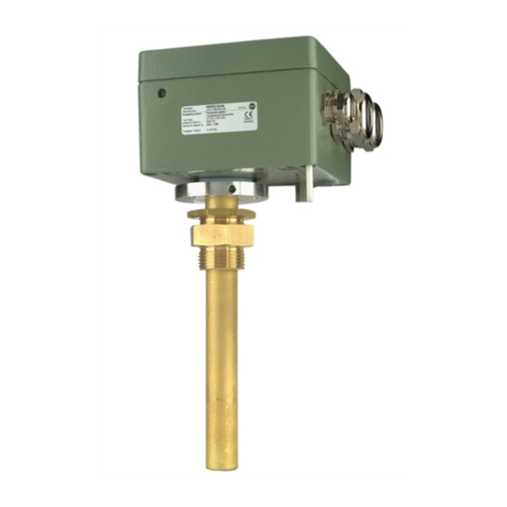
- Page 1 MESSKO ZT-F2.1 ® TRAFO-TEMPERATURGEBER TRANSFORMER TEMPERATURE TRANSMITTER TRANSMETTEUR DE TEMPÉRATURE DU TRANSFORMATEUR EMISOR DE TEMPERATURA DEL TRANSFORMADOR Betriebsanleitung/Operating Instructions/Instructions d’opération/Instrucciones de Operación B A2 52 6 030/07 DE- EN-F R- ES...
-
Page 2: Table Des Matières
Inhaltsverzeichnis/Contents/Table des matière/Índice Inhaltsverzeichnis Contents Sicherheit........4 Safety ........10 Sicherheitshinweise . - Page 3 Inhaltsverzeichnis/Contents/Table des matière/Índice Table des matière Índice Sécurité ........16 Seguridad.
-
Page 4: Sicherheit
Sicherheit Produktbeschreibung Sicherheit Bei der elektrischen Installation sind die nationalen Vor- schriften zu beachten. Um einen störungsfreien Betrieb zu Sicherheitshinweise gewährleisten, ist der Schutzleiter unbedingt anzuschließen. Alle Personen, die mit der Montage, Inbetriebnahme, ACHTUNG Bedienung, Wartung und Instandhaltung des Geräts zu tun haben, müssen Einbau, elektrischer Anschluss, Inbetriebnahme und Wartung des Geräts dürfen ausschließlich von... -
Page 5: Einbaubedingungen Und Test
Einbaubedingungen und Test Zeigerthermometer Montage 4. ZT-F2.1 ist in die Thermometertasche montiert. 5. Pt100 oder 4...20 mA-Ausgang (optional) ist angeschlossen (siehe Kap. 6.2/6.3). Fühler des Zeigerthermometers ist bis zum Anschlag einge- schoben (ca. 215 mm). 6. Die Badtemperatur sollte 30°C nicht überschreiten, da sonst die Wärmeabstrahlung über die Doppelverschraubung die Trafobedingungen verfälschen würde. -
Page 6: Elektrischer Anschluss
Elektrischer Anschluss Einstellen des Heißpunktgradienten 2-Leiter-Technik und Druckring entfernen. Druckschraube und Dichtung über den Temperaturfühler (Ø 9,5mm) und die Kapillarleitung schie- Bei einem Anzeigeinstrument in 2-Leiter-Technik (2 Messlei- ben. Temperaturfühler 40-50cm durch die kleine Kabelver- tungen) wird eine Messleitung an Klemme 3 und die andere an schraubung fädeln und bis zum Anschlag (ca. -
Page 7: Einstellung Für Ct-Nennstrom ≠ 2A
Einstellen des Heißpunktgradienten CT-Nennstrom) die Stellung der Schalter S1 und S2 bestimmen und diese entsprechend einstellen (siehe Bild 3). Der Heißpunktgradient kann von 4 K bis 50 K in 1 K-Schritten eingestellt werden. Für einen Heißpunktgradienten von z. B. 25 K ist die in Bild 3, Pos. -
Page 8: Anzeigekontrolle
Anzeigekontrolle Überspannungsschutz Service Technische Daten Wartung Technische Daten Liegt der Schnittpunkt von CT-Nennstrom und Soll-Tempera- turgradient zwischen zwei der abgebildeten Kurven, so ist die Abmessungen: siehe Anhang Kap 13.1 erforderliche Kurve zu interpolieren oder die oben erwähnte Werkstoffe: Formel zu verwenden, um den einzustellenden Wert zu Gehäuse/Anschluss-Box: Aluminiumlegierung, Druckguss ermitteln. - Page 9 Technische Daten Bild 5 BA2526030-07...
-
Page 10: Safety
Safety Product specification Safety CAUTION Safety instructions Installation, electrical connection, commissioning, and All personnel involved in installation, commissioning, maintenance of the device may only be carried out by operation or maintenance of this equipment must: qualified, skilled personnel and only in accordance with these operating instructions. -
Page 11: Installation Conditions And Testing
Installation conditions and testing Dial-type thermometer Assembly 4. ZT-F2.1 installed in the thermometer pocket. 5. Pt100 or 4...20mA analog output (optional) is connected (refer to chap. 6.2/6.3). Insert the sensor of the dial thermometer until it reaches the stop (approx. 215 mm). 6. -
Page 12: Electrical Connection
Electrical connection Setting the hot-spot gradient screw and remove the pressure ring. Push the pressure screw nected to terminals 3 and 4 and the equalizing line to terminal and gasket over the temperature detector (9.5 mm diame- 3a (see figure 3, item 2). ter) and the capillary tube. -
Page 13: Setting For Ct Nominal Current ≠ 2A
Setting the hot-spot gradient the position of switches S1 and S2 for the desired gradients in the table in the appendix (chap. 12.2 - hot-spot gradient table for 2A CT nominal current) and set these accordingly (see figure 3). The hot-spot gradient can be set from 4 K to 50 K in increments of 1 K. -
Page 14: Checking The Display
Checking the display Overvoltage protection Service Technical Data Maintenance If necessary, round off the calculated value to a whole number Technical data since the value to be set from 4 K to 50 K can only be set in Dimensions: Refer to appendix, chap. - Page 15 Technical Data nominal hot-spot gradient [K] Fig. 5 BA2526030-07...
-
Page 16: Sécurité
Sécurité Spécification du produit Sécurité permise que lorsque ces composants sont hors tension ou bien protégés contre tout contact direct. Instructions de sécurité L’installation électrique est soumise aux règlements de sécurité Toutes les personnes impliquées dans l’installation, la mise en nationaux. -
Page 17: Instructions De Montage Et Essais De Fonctionnement
Instructions de montage et essais de fonctionnement Thermomètre a cadran Montage 50 ml d'huile à température ambiante (ne pas utiliser de papier aluminium ou autre). La précision de l‘affichage de la tempéra- ture du point chaud est subordonnée au strict respect de cette condition. -
Page 18: Montage Du Transmetteur De Température
Raccordement électrique Montage du transmetteur de température AVERTISSEMENT de transformateur ZT-F2.1 Le transmetteur de température de transformateur ZT-F2.1 est Tensions électriques très dangereuses! prévu pour être monté dans une poche à thermomètre selon la Avant l’ouverture de l’appareil, tous les câbles de norme DIN EN 50216-4 type A1. - Page 19 Raccordement électrique Fig. 2 raccordement s’effectue dans la technique bifilaire (R/L maxi 750 Ω sous 24 V CC), via les bornes 3a et 3 (voir Fig. 2 et Fig. 3, repère 2). Boucle de courant I1 comme sortie analogique passive : L’appareil se comporte comme une résistance variable où...
-
Page 20: Réglage Du Gradient De Température Du Point Chaud
Réglage du gradient de température Entretien Contrôle des valeurs affichées Protection de surtension Maintenance Caractéristiques techniques Réglage du gradient de température Maintenance du point chaud Affichage de gradient du point chaud trop élevé: Vérifiez s’il n’y a ne faire que de l’huile dans la poche à thermomètre. Réglage pour un TC courant nominal 2A Affichage de gradient du point chaud trop bas au ther- Le gradient de température du point chaud (à... - Page 21 Caractéristiques techniques Conditions d‘exploitation et conditions ambiantes: Courant nominal TC: 2 A du convertisseur Résistance aux surintensités: max. 3 A en permanence (correspond au courant nominal TC x 1,5); 12 A pour 30 sec. Réglage du gradient: au moyen des commutateurs DIP (voir chap.
- Page 22 Caractéristiques techniques Gradient de température du point chaud pour un TC courant nominal 2A Gradient de température [K] Fig. 5 BA2526030-07...
-
Page 23: Seguridad
Seguridad Descripción del producto Seguridad necesario conectar el equipo a tierra para garantizar una operación sin perturbaciones. Instrucciones de seguridad ATENCIÓN Toda persona involucrada en los trabajos de montaje, puesta en servicio, operación, y mantenimiento del aparato debe El montaje, la conexión eléctrica, la puesta en marcha y el mantenimiento del aparato deben ser realizados sólo - estar lo suficientemente tecnificado y cualificado y por personas cualificadas y preparadas siguiendo estas... -
Page 24: Condiciones De Montaje Y Prueba
Condiciones de montaje y prueba Termómetro de aguja Montaje las condiciones similares a las que existen en el transformador (véase el siguiente campo de “condiciones de prueba”). Condiciones de prueba 1. Baño de aceite regulado y removido. 2. El termopozo está montada en el baño de aceite. 3. -
Page 25: Conexión Eléctrica
Conexión eléctrica Llene el termopozo con aprox. 50 ml de aceite a temperatura Detector de temperatura resistivo Pt100 ambiente. Para efectuar el montaje, la tuerca inferior del doble El ZT-F2.1 está indicador aplicado un detector de temperatura atornillamiento (fig. 1, pos. 4) ha de enroscarse en la bolsa para resistivo Pt100 según IEC 751. -
Page 26: Ajuste Del Gradiente Del Punto Caliente
Ajuste del gradiente del punto caliente En lugar del detector de temperatura resistivo Pt100, el ZT-F2.1 se suministra con una salida analógica 4...20mA. La conexión se realiza en la técnica de 2 conductores (D/I máx. 750 Ω a 24 V DC) a través de los bornes 3a y 3 (ver fig. -
Page 27: Ajuste Para Corriente Nominal Ct ≠ 2A
Control de indicación Protección contra Servicio sobretensiones Mantenimiento Datos técnicos Mantenimiento Por ejemplo para un gradiente de punto caliente de 25 K es preciso ajustar la posición del interruptor representada en la El emisor de temperatura del transformador ZT-F2.1 no fig. - Page 28 Datos técnicos Temperatura ambiental: -50... +85° C Colocación: puede instalarse en interiores o al aire libre, resistente a ambientes tropicales Calefacción: Integrada en el manguito . 4,5 Ω Potencia CT: P [VA] = I Posicionamiento: Arbitrario Tensión de aislamiento nominal: 300 VAC, 50 Hz Señal de salida analógica: Hasta 2x para PT100 / PT1000...
- Page 29 Datos técnicos Gradiente teórico del punto caliente [K] Figura 5 BA2526030-07...
-
Page 30: Anhang
Anhang / Appendix / Annexe / Anexo Anhang / Appendix / Annexe / Anexo 13.1 Abmessungen / Dimensions / Mesurage / Dimensiones ca. 143 / approx. 5.64" 122 / 4.80" 120 / 4.72" SW41 DIN 475 Belüftung/ G1B DIN ISO 228 Ventilation/ Ventilation/ Ventilacion... -
Page 31: Tableau Des Gradients De Température Du Point Chaud Pour Le Tc Courant Nominal 2A
Anhang / Appendix / Annexe / Anexo 13.2 Heißpunktgradienten-Tabelle für 2A CT-Nennstrom/Hot-spot gradient table for 2A CT nominal current/Tableau des gradients de température du point chaud pour le TC courant nominal 2A/Tabla de gradientes del punto caliente para corriente nominal CT 2A Gradient/Gradient/ Gradient/Gradient/ Gradient/Gradiente... - Page 32 Anhang / Appendix / Annexe / Anexo Gradient/Gradient/ Gradient/Gradient/ Gradient/Gradiente Gradient/Gradiente BA2526030-07...
- Page 33 Anhang / Appendix / Annexe / Anexo Gradient/Gradient/ Gradient/Gradient/ Gradient/Gradiente Gradient/Gradiente BA2526030-07...
-
Page 34: Sensor Sustitutivo
Anhang / Appendix / Annexe / Anexo 13.3 Ersatzfühler (Zubehör) / Replacement sensor (accessory) / Élément détecteur de remplacement (accessoire) / Sensor sustitutivo (accesorio) Bild 7/Fig. 7/Figura 7 BA2526030-07... - Page 36 Messko GmbH Gewerbegebiet An den Drei Hasen Messko-Platz 1, 61440 Oberursel, Germany Phone: +49 6171 6398-0 Fax: +49 6171 6398-98 Email: messko-info@reinhausen.com www.reinhausen.com/messko Bitte beachten: Die in allen unseren Publikationen enthaltenen Angaben können in Details von dem gelieferten Gerät abweichen. Änderungen bleiben vorbehalten.