Publicité
Liens rapides
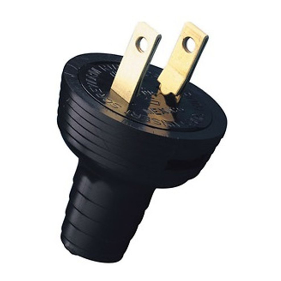
Cat. Nos. 48642, 48643
• For lamps and small appliances
WARNINGS AND CAUTIONS
• TO AVOID FIRE, SHOCK, OR DEATH; TURN OFF POWER AT CIRCUIT BREAKER OR FUSE AND TEST THAT POWER IS OFF BEFORE WIRING!
• To be installed and/or used in accordance with appropriate electrical codes and regulations.
• If you are unsure about any part of these instructions, consult an electrician.
• Use this device with copper or copper clad wire only.
• For indoor applications only.
INSTALLATION
CAT. NO. 48642
CAUTION: DO NOT cut or DAMAGE cord jacket or insulation except where indicated.
NOTE: Use with 2-wire flexible cords 3/8" (.9 cm) maximum diameter, 18-2 to 14-2 AWG.
NOTE: Underwriter's Knot recommended to reduce possible cord strain that could loosen terminal connections.
1. Pry body out of cover (Diagram A, Fig. 1).
2. Feed cord through cover (Diagram A, Fig. 2).
3. Remove cord jacket and separate conductors (Diagram A, Fig. 3).
4. Tie Underwriter's Knot and pull tight (Diagram A, Fig. 4). Cut conductors to size indicated.
5. Remove insulation from end of each conductor to expose 1/2" (1.3 cm) copper strands (Diagram A, Fig. 5).
6. Connect conductors to terminal screws as follows (Diagram A, Fig. 5):
NOTE: Back out terminal screws until they stop turning (do not force past this point).
• Twist copper strands of each conductor tightly together.
• Loop conductor clockwise, 3/4 turn around terminal screw and tighten screw securely.
• Cut off any wire strands not secure under terminal screw.
7. Seat UL knot and push body into cover until both tabs lock in slots (Diagram A, Fig. 6).
CAT. NO. 48643
CAUTION: DO NOT cut or DAMAGE cord jacket or insulation except where indicated.
NOTE: Use with 2-wire flexible cords 3/8" (.9 cm) maximum diameter, 18-2 to 14-2 AWG.
1. Pry body out of cover (Diagram B, Fig. 1).
2. Feed cord through cover (Diagram B, Fig. 2).
3. Remove cord jacket and conductor insulation (Diagram B, Fig. 3).
4. Connect conductors to terminal screws as follows (Diagram B, Fig. 4):
NOTE: Back out terminal screws until they stop turning (do not force past this point).
• Twist copper strands of each conductor tightly together.
• Loop conductor clockwise, 3/4 turn around terminal screw and tighten screw securely.
• Cut off any wire strands not secure under terminal screw.
5. Push body into cover until both tabs lock in slots (Diagram B, Fig. 5).
DIAGRAM / SCHÉMA / DIAGRAMA A - Cat. 48642
Fig. 1
Cover
Body
Coquille
Corps
Cubierta
Cuerpo
Fig. 3
Round cord
2-3/4"
Cordon rond
2-3/4 po
Cordón redondo
7 cm
Flat cord (no jacket)
2-3/4"
Cordon plat (sans gaine)
2-3/4 po
Cordón plano (sin forro)
7 cm
Fig. 5
1/2"
1/2 po
1.3 cm
DIAGRAM / SCHÉMA / DIAGRAMA B - Cat. 48643
Fig. 1
Cover
Body
Coquille
Corps
Cubierta
Cuerpo
Fig. 3
Insulation
Copper strands
Isolant
Brins de cuivre
Aislante
Hilos de cobre
1/2"
Round cord
1/2 po
Cordon rond
1.3 cm
Cordón redondo
1-1/4"
1-1/4 po
3 cm
Fig. 4
Cover
Body
Coquille
Corps
Cubierta
Cuerpo
FOR CANADA ONLY
For warranty information and/or product returns, residents of Canada should contact Leviton in writing at Leviton Manufacturing of Canada Ltd to the attention of the Quality Assurance Department, 165 Hymus Blvd, Pointe-Claire
(Quebec), Canada H9R 1E9 or by telephone at 1 800 405-5320.
Leviton warrants to the original consumer purchaser and not for the benefit of anyone else that this product at the time of its sale by Leviton is free of defects in materials and workmanship under normal and proper use for two years from the
purchase date. Leviton's only obligation is to correct such defects by repair or replacement, at its option. For details visit www.leviton.com or call 1-800-824-3005. This warranty excludes and there is disclaimed liability for labor for removal of
this product or reinstallation. This warranty is void if this product is installed improperly or in an improper environment, overloaded, misused, opened, abused, or altered in any manner, or is not used under normal operating conditions or not in
accordance with any labels or instructions. There are no other or implied warranties of any kind, including merchantability and fitness for a particular purpose, but if any implied warranty is required by the applicable jurisdiction, the duration
of any such implied warranty, including merchantability and fitness for a particular purpose, is limited to two years. Leviton is not liable for incidental, indirect, special, or consequential damages, including without limitation, damage to,
or loss of use of, any equipment, lost sales or profits or delay or failure to perform this warranty obligation. The remedies provided herein are the exclusive remedies under this warranty, whether based on contract, tort or otherwise.
© 2015 Leviton Mfg. Co., Inc.
Straight Blade Plugs and Connectors
Rated: 15A - 125V
Fig. 2
Cover
Coquille
Cubierta
Fig. 4
Round cord
Cordon rond
Cordón redondo
1"
1 po
2.5 cm
End of jacket
Fin de la gaine
Final del forro del cordón
Punto de separación
Fig. 6
Tab in slot
Patte dans la fente
Pestaña en la ranura
Fig. 2
Cover
Coquille
Cubierta
Insulation
Copper strands
Isolant
Brins de cuivre
Aislante
Hilos de cobre
Flat cord (no jacket)
1/2"
Cordon plat (sans gaine)
1/2 po
Cordón plano (sin forro)
1.3 cm
1-1/4"
1-1/4 po
3 cm
Fig. 5
Tab in slot
Patte dans la fente
Pestaña en la ranura
LIMITED 2 YEAR WARRANTY AND EXCLUSIONS
For Technical Assistance Call: 1-800-824-3005 (U.S.A. Only) www.leviton.com
INSTALLATION INSTRUCTIONS
CAT. NO. 48646
CAUTION: DO NOT cut or DAMAGE cord jacket or insulation except where indicated.
NOTE: Use with 2-wire flexible round cords 7/16" (1 cm) maximum diameter, 18-2 to 14-2 AWG.
1. Pry body out of cover (Diagram C, Fig. 1).
2. Feed cord through cover (Diagram C, Fig. 2).
3. Remove cord jacket and conductor insulation (Diagram C, Fig. 3).
4. Connect conductors to terminal screws as follows (Diagram C, Fig. 4):
NOTE: Back out terminal screws until they stop turning (do not force past this point).
• Twist copper strands of each conductor tightly together.
• Loop conductor clockwise, 3/4 turn around terminal screw and tighten screw securely.
• Cut off any wire strands not secure under terminal screw.
5. Push body into cover until both tabs lock in slots (Diagram C, Fig. 5).
6. Alternately tighten clamp screws until cord is gripped securely (Diagram C, Fig. 5).
CAT. NO. 48648
CAUTION: DO NOT cut or DAMAGE cord jacket or insulation except where indicated.
NOTE: Use with 3-wire flexible round cords 7/16" (1 cm) maximum diameter, 18-3 to 16-3 AWG.
1. Pry body out of cover (Diagram D, Fig. 1).
2. Feed cord through cover (Diagram D, Fig. 2).
3. Remove cord jacket and conductor insulation (Diagram D, Fig. 3).
4. Connect conductors to terminal screws as follows (Diagram D, Fig. 4):
NOTE: Back out terminal screws until they stop turning (do not force past this point).
• BLACK (Hot) wire to BRASS screw, WHITE (Neutral) wire to SILVER screw, and GREEN (Ground) wire to
GREEN screw.
• Twist copper strands of each conductor tightly together.
• Loop conductor clockwise, 3/4 turn around terminal screw and tighten screw securely.
• Cut off any wire strands not secure under terminal screw.
5. Push body into cover until both tabs lock in slots (Diagram D Fig. 5).
6. Alternately tighten clamp screws until cord is gripped securely (Diagram D, Fig. 5).
DIAGRAM / SCHÉMA / DIAGRAMA C - Cat. 48646
Fig. 1
Cover
Cord
Coquille
Cordon
Cubierta
Cordón
Flat cord
Cordon plat
Cordón plano
1"
1 po
2.5 cm
Separation point
Point de séparation
Fig. 4
DIAGRAM / SCHÉMA / DIAGRAMA D - Cat. 48648
Fig. 1
Cord
Cover
Cordon
Coquille
Cordón
Cubierta
Fig. 4
White wire to
silver screw
Fil blanc à la
vis argent
Conductor blanco al
tornillo plateado
Green wire to
green screw
Fil vert à la vis verte
Conductor verde al tornillo verde
Cat. Nos. 48646, 48648
Rated: 15A - 125V
• For power tools and large appliances
• Cord clamp relieves strain on wiring terminals
Fig. 2
Body
Cover
Corps
Coquille
Cuerpo
Cubierta
Fig. 3
Insulation
Copper strands
Isolant
Brins de cuivre
Aislante
Hilos de cobre
3/4"
3/4 po
2 cm
1-1/2"
1-1/2 po
3.8 cm
Fig. 5
Cord clamp screw
Vis de collier
Tornillos de la
abrazadera
del cordón
Fig. 2
Body
Cover
Corps
Coquille
Cuerpo
Cubierta
Insulation
Copper strands
Fig. 3
Isolant
Brins de cuivre
Aislante
Hilos de cobre
3/4"
3/4 po
2 cm
1-1/2"
1-1/2 po
3.8 cm
Fig. 5
Black wire to brass
screw
Fil noir à la vis laiton
Conductor negro al
tornillo de latón
Cord clamp screw
Vis de collier
Tornillos de la
abrazadera
del cordón
PK-93287-10-02-0D
ENGLISH
Cord
Cordon
Cordón
Tab in slot
Patte dans la fente
Pestaña en la ranura
Cord
Cordon
Cordón
Tab in slot
Patte dans la fente
Pestaña en la ranura
PK-93287-10-02-0D
Publicité

Manuels Connexes pour Leviton 48646

Sommaire des Matières pour Leviton 48646
- Page 1 Leviton warrants to the original consumer purchaser and not for the benefit of anyone else that this product at the time of its sale by Leviton is free of defects in materials and workmanship under normal and proper use for two years from the purchase date. Leviton’s only obligation is to correct such defects by repair or replacement, at its option. For details visit www.leviton.com or call 1-800-824-3005. This warranty excludes and there is disclaimed liability for labor for removal of this product or reinstallation.
- Page 2 TELEFONO: 2. La empresa se compromete a reemplazar o cambiar el producto defectuoso sin ningún cargo para el consumidor, los gastos de transportación que se deriven de su cumplimiento serán cubiertos por: LEVITON, S. de R.L. de C.V. DATOS DE LA TIENDA O VENDEDOR...