Publicité
Les langues disponibles
Les langues disponibles
Liens rapides
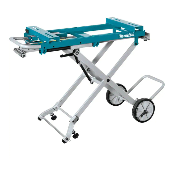
Miter saw stand
GB
F
Chariot Pour Scie à Coupe
d'Onglet
D
Untergestell
I
Supporto per sega circolare
NL
Verstekzaagtafel
E
Base para Sierra de Banco
BZ
Mesa para Serra de Esquadria Manual de Instruções
WST05
Instruction manual
Manuel d'instructions
Betriebsanleitung
Istruzioni per l'uso
Gebruiksaanwijzing
Manual de instrucciones
Publicité

Sommaire des Matières pour Makita WST05
- Page 1 Miter saw stand Instruction manual Chariot Pour Scie à Coupe Manuel d’instructions d’Onglet Untergestell Betriebsanleitung Supporto per sega circolare Istruzioni per l’uso Verstekzaagtafel Gebruiksaanwijzing Base para Sierra de Banco Manual de instrucciones Mesa para Serra de Esquadria Manual de Instruções WST05...
- Page 2 11-1...
- Page 3 34 33...
-
Page 4: Preparation
Inclusive of models followed by F, L and FL, if any. Preparation Note: Check contents of package for the following components. Please inform Makita service center of any part missing in the package immediately. • Miter saw stand (1 unit) •... - Page 5 4. To stabilize the stand, loosen the round nut (25) and turn the adjusting feet (24). Retighten the round nut (25) after the setting. Folding: (Fig. 4) 1. Place your foot on the support (14). 2. Slightly pull up the handle (23) with both hands and pull the release lever (26).
-
Page 6: Montage Du Chariot Pour Scie À Coupe D'onglet : (Fig. 1)
Préparation Remarque : vérifiez que l’emballage contient les composants suivants. Veuillez informer immédiatement le centre de réparation de Makita si une pièce manque dans l’emballage. • Chariot pour scie à coupe d’onglet (1 pièce) • Pied avant G (1 pièce) •... -
Page 7: Montage De La Scie À Coupe D'onglet Sur Son Chariot : (Fig. 2)
Montage de la scie à coupe d’onglet sur son chariot : (Fig. 2) Libérez les leviers (16). Placez la scie à coupe d’onglet de façon que les taraudages de la base de la scie correspondent à ceux du plateau. Fixez le chariot pour scie à... - Page 8 Einschließlich der Modelle mit F, L und FL. Vorbereitung Hinweis: Prüfen Sie den Inhalt des Pakets auf die folgenden Komponenten. Wenden Sie sich sofort an das Makita- Servicecenter, falls ein Teil des Pakets fehlt. • Untergestell für Kapp- und Gehrungssäge (1 Einheit) •...
- Page 9 Aufbewahren des Verlängerungsarms: kann in einem anderen Winkel angepasst werden, indem dieser angehoben und in den gewünschten (Abb. 5 und 6) Winkel gedreht wird. Befolgen Sie die Vorgehensweise „Einstellen der Verlängerungsarme“ in umgekehrter Reihenfolge. Befestigen einer Kapp- und Gehrungssäge auf dem Untergestell: (Abb.
- Page 10 Preparazione Nota: verificare che nella confezione siano contenuti i componenti indicati di seguito. Rivolgersi immediatamente al centro assistenza Makita in caso di mancanza di componenti nella confezione. • Supporto per sega circolare (1 unità) • Piede anteriore S (1 unità) •...
- Page 11 M8 x 50 (17) (4 pz.), la rondella piatta 8 (18) (8 pz.) e il dado esagonale 8 (19) (4 pz.). Fissare le leve (16). Nota: utilizzare i fori piccoli nei tavoli di lavoro come scale per impostare correttamente la sega circolare. Impostazione: (Fig.
- Page 12 Tevens indien deze modelnummers gevolg worden door F, L of FL. Voorbereidingen Opmerking: Controleer de inhoud van de verpakking op aanwezigheid van de volgende onderdelen. Neem onmiddellijk contact op met een Makita-servicecentrum in het geval enig onderdeel in de verpakking ontbreekt. • Verstekzaagtafel (1 stuk) • Voorpoot L (1 stuk) •...
- Page 13 De verstekzaag monteren op de verstekzaagtafel: (zie afb. 2) Zet de hendels (16) los. Plaats de verstekzaag zodanig dat de boutgaten in de voet van de verstekzaag samenvallen met de boutgaten in de werktafel. Bevestig de verstekzaagtafel met de zeskantbouten M8 x 50 mm (17) (4 stuks), platte ring 8 mm (18) (8 stuks) en zeskantmoer 8 mm (19) (4 stuks).
- Page 14 Fije la palanca en el extremo del eje de la proporcionan en dos de los cuatro pies. rueda y, a continuación, apriete la tuerca hexagonal 8 • Sólo se debe utilizar con el modelo de Makita indicado (1). en el manual de instrucciones.
- Page 15 solapen con los orificios de la mesa de trabajo. Fije la base para sierra de banco con el perno hexagonal M8 x 50 (17) (4 piezas), la arandela plana 8 (18) (8 piezas) y la tuerca hexagonal 8 (19) (4 piezas). Fije las palancas (16). Nota: utilice los pequeños orificios en las mesas de trabajo como referencia para ajustar correctamente la sierra de banco.
- Page 16 Inclusive os modelos seguidos de F, L e FL, se houver. Preparação Nota: Verifique o conteúdo da embalagem quanto aos seguintes componentes. Informe imediatamente ao centro de assistência Makita se alguma peça estiver faltando na embalagem. • Mesa para serra de esquadria (1 unidade) • Pé frontal E (1 unidade) •...
- Page 17 Nota: Use pequenos orifícios nas mesas de trabalho como escalas para ajustar a serra de esquadria corretamente. Instalação: (Fig. 3) 1. Pressione a empurradura (23) para baixo e coloque seu pé no suporte (14). 2. Libere a alavanca de travar (22). 3.
- Page 20 Makita Corporation Anjo, Aichi, Japan www.makita.com JM23480007...


