Publicité
Liens rapides
CANADA
Yorkville Sound
550 Granite Court
Pickering, Ontario
L1W-3Y8 CANADA
Voice: (905) 837-8481
Fax: (905) 837-8746
www.vtcproaudio.com
U.S.A.
Yorkville Sound Inc.
4625 Witmer Industrial Estate
Niagara Falls, New York
14305 USA
Voice: (716) 297-2920
Fax: (716) 297-3689
NS21P
SMT Disclaimer
Due to the complex nature of the use of SMT installed components
in Yorkville equipment, we highly caution all service technicians in
attempting to repair or replace SMT factory installed components.
Many of these components may be glued prior to initial soldering.
Replacing SMT components requires expensive
specialized de-soldering equipment and training.
Yorkville Sound will repair and replace defective SMT components
to ensure proper quality assurance and installation is maintained.
Service Manual
Manual-Service-VTC-NS21P-00-1v3 • November 1, 2018
Publicité

Sommaire des Matières pour VTC Pro Audio NS21P
- Page 1 Replacing SMT components requires expensive Fax: (905) 837-8746 Fax: (716) 297-3689 specialized de-soldering equipment and training. Yorkville Sound will repair and replace defective SMT components to ensure proper quality assurance and installation is maintained. Service Manual www.vtcproaudio.com Manual-Service-VTC-NS21P-00-1v3 • November 1, 2018...
- Page 2 IM PORTAN T S A F E TY I NS TRU C TI ONS This lightning flash with arrowhead symbol, within The exclamation point within an equilatereal triangle is intended to alert the an equilateral triangle, is intended to alert the user to the presence of user to the presence of important operating and maintenance (servicing) uninsulated “dangerous voltage”...
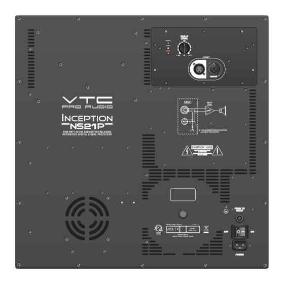
- Page 3 NS21P LEVEL POWER LIMIT CLIP INPUT OUTPUT NS21P LEVEL LINK CONNECTIONS FUNCTION 2400 WATT ACTIVE SUBWOOFER ENCLOSURE AS INPUT OR OUTPUT. INTEGRATED DIGITAL SIGNAL PROCESSOR PUSH TO RESET MODEL TYPE: YS1074 A-Z1206B / 1v1 230V 120VAC 50Hz 6,0A 60Hz 12.0A MANUFACTURED BY YORKVILLE SOUND •...
- Page 4 Specifications - NS21P System Type Rear Horn Loaded Subwoofer Active or Passive Active 2400 Program Power (Watts) Max SPL (dB) Frequency Response (Hz +/- 3db) 32 - 150 LF Driver(s) Single 21 inch with 6 inch voicecoil LF Program Power(Watts)
- Page 5 Spécifications - NS21P Type de système Caisson subwoofer avec chargement arrière du pavillon Active ou Passive Active 2400 Puissance Nominale (Watts) Niveau de Pression Sonore Max (dB) Réponse en Fréquence (Hz +/- 3db) 32 - 150 Haut-Parleur - Fréquences Graves...
- Page 6 NS21P LINE / SPKR LOUD DEEP LEVEL SHAPE HF ROLLOFF MONO BLEND INPUT...
- Page 8 YS # Description YS # Description YS # Description R170 4832 W250 22K T&R RES 2010 W167 10R0 2%FLAME PROOF T&R RES 6432 1N5248B 18V0 0W5 ZENER 5% T&R R171 4832 W250 22K T&R RES 6136 W250 3K3 5%MINI T&R RES 6432 1N5248B 18V0 0W5 ZENER 5% T&R R172...
- Page 9 BLACK W5:D TO SPEAKER - W5:C W6:D 4 BLACK 4080 2.0UH W6:C 4 250V 6500 275V 2.7mH W6:B 4 250V 2.0UH 4080 W6:A 4 100V 400V W5:B TO SPEAKER + W5:A M1373PCB_DATABASE_HISTORY MODEL(S):- CROW BAR DATE VER# DESCRIPTION OF CHANGE 07-JAN-2009 1.00 FIRST DESIGN 14DEC09...
- Page 10 M1373 V3.00 EMC FILTER 275V 5262 4080 2.0UH CLINCH 2ozCopper INSERT ORIGIN LONG AXIS ORIGIN M1373 V3.00 SEE LAYOUT DOCUMENTATION...
- Page 11 SEE LAYOUT DIAGRAM M1373 V3.00 PRODUCTION NOTES M1373PCB_DATABASE_HISTORY MODEL(S):- CROW BAR DATE VER# DESCRIPTION OF CHANGE 07-JAN-2009 1.00 FIRST DESIGN 14DEC09 2.00 PC#7925 CHANGE L4, L5 FROM YS#3769 TO YS#4080 09-FEB-2010 3.00 PC7993: Reduce panel to 3x5 boards...
-
Page 12: Power Supply
POWER SUPPLY POWER AMP M1375 3/3 M1375 1/3 +15V_LS Thermal Breaker ACDETECT 96 DEG C +130V -130V PSGND +15V -15V Product LS2100P/NS21P LS2100P/NS21P PCB# M1375 Sheet Date: Mon Feb 06, 2017 Rev: Filename: M1375V08sch.sch2006... - Page 13 RIBBON_GND 18uH SPACER GROUND U4:C U27:C U7:C U19:C U25:C U1:C U18:C U6:C 3899 1N5248B U40:C U5:C (VCC) Product LS2100P/NS21P 100N HERE LM13600N 18V0 U15:D MINI 4148 6745 Dual VCA -15VIP {Function} LS2100P/NS21P PCB# M1375 Sheet -15VIP ADD MORE BYPASS CAPS...
- Page 14 +15V_LS+ 100N 100N 100N SIG_GND PSGND 74HC14N SIG_GND U17:C U24:C U12:C -15V_U12 6603 100N 200V 18uH R101 R124 3899 Product LS2100P/NS21P -15V_MOD 1/8W -15V_U12 1/8W U20:E -15V -15V 10R0 10R0 -15V -15V_U12 -15V_MOD +15V_LS- FLMP 74HC14N FLMP SIG_GND -15V -15V...
- Page 15 CIRCUIT -15V_U21 -15V_TRI FLMP FLMP 100N PSGND 6640 ON AMP PCB R160 -15V_TRI 100N 100N R174 -15V_U21 MINI Product LS2100P/NS21P MINI 200V -15V_U21 GND-TRI LS2100P/NS21P PCB# M1375 Sheet +15V_TRI GND-TRI GND-TRI GND-TRI Date: Mon Feb 06, 2017 Rev: Filename: M1375V08sch.sch2006...
- Page 16 100N 100N 100N 100N 150P 681R0 150P R T V R165 R T V BAT85 R175 TIP-SW TIP-SW 470P C118 681R0 BAT85 LS2100P/NS21P R180 R117 BAT85 M1375 IRS2184 R195 IRS2184 250V 250V R193 R192 2.0W 5953 5953 180K C105 0.4"Fins...
- Page 17 SEE LAYOUT DIAGRAM M1375 NS21P PRODUCTION NOTES 1. LEDS LD1, LD2, AND LD3 ARE TO BE HAND INSERTED. 2. INSTALL YS#8937 TIE AROUND C104. SEE PIC. 3. RTV ALL ELECTROLYTIC CAPACITORS. 4. PCBSA: DO NOT STUFF J3, J5. J7, P2, P3, OR S1...
- Page 18 14-JAN-2015 PC#8734:D12 and D14 added to U30,U31 regulators. FOD816 (YS#2306) 16-JUN-2015 PC8811: Add NS21P product used on. GG 17-JAN-2017 PC8988: Change C81, C82, C85, and C86 to 1N YS#5220 19-JAN-2017 V08 PC8988: Implemented on board...
- Page 19 Yorkville Sound 550 Granite Court Pickering, Ontario Canada L1W 3Y8 www.yorkville.com Auto Attend: (905) 837-8550 Fax: (905) 837-8746...

