Publicité
Les langues disponibles
Les langues disponibles
Liens rapides
Manuale d'installazione, uso e manutenzione
Installation, use and maintenance manual
Manuel d'installation, d'utilisation et d'entretien
Installations-, Bedienungs- und Wartungsanleitung
Manual de instalación, uso y mantenimiento
Stufa a pellet mod - Pellet stove model - Poêle à granulés mod.
Pelletofen Modell - Estufa de pellets mod.
SPRINT** acciaio
Leggere attentamente le istruzioni prima dell'installazione, utilizzo e manutenzione.
Read the instructions carefully before installation, use and maintenance.
Lire attentivement les instructions avant d'installer, d'utiliser et d'entretenir le poêle.
Vor Installation, Gebrauch und Wartung muss diese Anleitung aufmerksam durchgelesen werden.
Das Handbuch ist wesentlicher Bestandteil des Geräts.
Lea atentamente las instrucciones antes de realizar la instalación, el uso y el mantenimiento.
Il manuale è parte integrante dell'apparecchio.
The manual is an integral part of the unit.
Le manuel fait partie intégrante de l'appareil.
El manual es parte integrante del equipo.
1
484210571-M5_07/13
Hardware - M
SPRINT** acciaio
Publicité

Sommaire des Matières pour Cola SPRINT acciaio
- Page 1 Manuale d’installazione, uso e manutenzione Installation, use and maintenance manual Manuel d’installation, d'utilisation et d'entretien Installations-, Bedienungs- und Wartungsanleitung Manual de instalación, uso y mantenimiento Stufa a pellet mod - Pellet stove model - Poêle à granulés mod. Pelletofen Modell - Estufa de pellets mod. SPRINT** acciaio 484210571-M5_07/13 Hardware - M...
- Page 2 5-33 ............................. La Ditta COLA garantisce i propri prodotti secondo le norme attualmente in vigore , ad esclusione delle parti soggette a normale usura . Per le condizioni di garanzia rivolgersi all’importatore o al rappresentante autorizzato, il quale può integrare il periodo della garanzia obbligatoria con un periodo supplementare a sua totale ed esclusiva responsabilità.
- Page 3 SPRINT** acciaio...
- Page 4 SPRINT** acciaio...
- Page 5 AVVERTENZE GENERALI 4.7 Regolazione flussi uscita aria 1.1 Introduzione calda 1.2 Come utilizzare il manuale 4.8Termostato – cronotermostato 1.3 Norme di sicurezza esterno 1.4 Descrizione tecnica 4.9 Periodo di inattività (fine stagione) 1.5 Combustibile e uso consentito 1.6 Accessori in dotazione PULIZIA DELLA STUFA 1.7 Riferimenti normativi 5.1 Pulizia braciere...
- Page 6 1 AVVERTENZE GENERALI 1.1 Introduzione Gentile Cliente , Desideriamo innanzi tutto ringraziarLa per la fiducia accordataci acquistando un nostro prodotto. La invitiamo a leggere e seguire attentamente i consigli contenuti in questo manuale d’installazione, uso e manutenzione al fine di poter sfruttare al meglio le qualità...
- Page 7 1.4 Descrizione tecnica La stufa funziona esclusivamente a pellet e diffonde nell’ambiente un calore sano e sicuro. I sistemi di controllo automatici di cui è dotata garantiscono una resa termica ottimale ed una combustione completa , inoltre sono presenti dei sistemi di sicurezza atti a garantire un funzionamento sicuro sia per i componenti della stufa sia per l’utente.
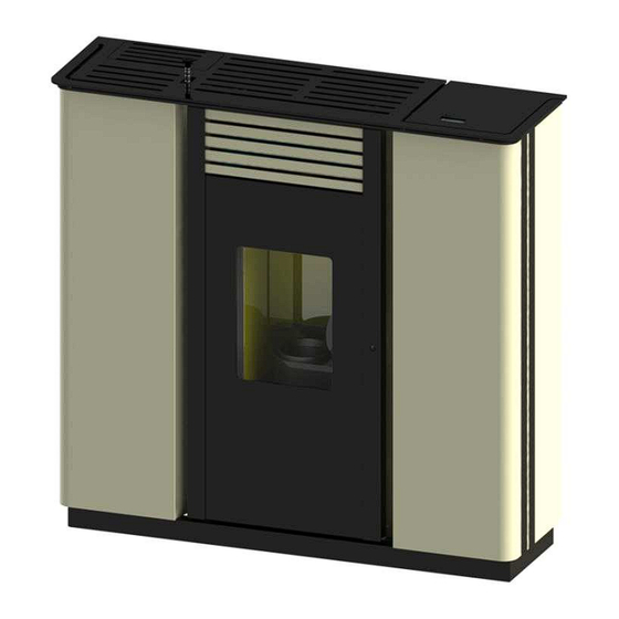
- Page 8 Ingombri stufa pellet SPRINT** acciao Legenda: 1-Griglie passaggio aria 2-Allacciamento cavo elettrico 3-Aspirazione aria comburente Ø 50 mm 4-Allacciamento standard tubo scarico fumi Ø 80mm 4.1-Predisposizione uscita posteriore scarico fumi 5-Sportello serbatoio pellet 6-Pannello comandi mod. F047 7-Attacco uscita superiore aria canalizzata Ø 80 mm 7.1-Predisposizione uscita canalizzazione posteriore Ø...
- Page 9 Per aprire la porta inserire la maniglia in dotazione e ruotare Maniglia apertura-chiusura in senso orario porta fuoco ; - Apertura: senso orario - Chiusura: senso antiorario 1.5 Combustibile e uso consentito Le stufe a pellet funzionano esclusivamente con pellet (pastiglie) di varie essenze di legno conformi alla normativa DIN plus 51731 o UNI CEN/TS 14961 o Ö-Norm M 7135 ovvero aventi le seguenti caratteristiche: Potere calorico min 4.8 kWh/kg (4180 kcal/kg)
- Page 10 Norma CEI EN 55014-2 : Resistenza elettromagnetica – Requisiti per elettrodomestici, attrezzi elettrici e apparecchi elettrici simili – Parte 2: Immunità ; Norma famiglia di prodotti ; Norma CEI EN 61000-3-2 : Limiti per le emissioni di corrente armonica ( Corrente ingresso ≤16 A per fase ) ; Norma CEI EN 61000-3-3 : Limitazione delle fluttuazioni di tensione e del flicker in sistemi di alimentazione in bassa tensione per apparecchiature con corrente nominale ≤...
- Page 11 Comignolo A = 200 antivento B = 200 C = 1500 Canna D = 200 fumaria Raccordo fumi Presa d’aria min. 100 cm² Base salva-pavimento Ogni installazione deve prevedere uno spazio tecnico di manovra di facile accesso per le manutenzioni periodiche . La stufa è...
- Page 12 2.3 Presa d’aria L’attacco di aspirazione o presa d’aria della stufa è collocato posteriormente ed è di sezione circolare con diametro pari a 50 mm. Nel locale dove viene installata la stufa deve affluire una quantità d’aria almeno pari a quello necessaria alla combustione ;...
- Page 13 2.5 Controllo posizione braciere e deviatore Prima di accendere la stufa è importante controllare che il braciere sia in posizione corretta ovvero alloggi negli appositi incastri . Inoltre controllare che il deviatore fumi superiore sia incastrato nella propria sede. Una posizione errata del deviatore comporta malfunzionamenti ed un eccessivo annerimento del vetro .
- Page 14 2.7 Collegamento elettrico Collegare il cavo di alimentazione elettrica da una parte alla presa della stufa presente sul lato anteriore interno del serbatoio e dall’altra su una presa elettrica a parete . La tensione fornita dall’impianto deve corrispondere a quella indicata sulla targhetta di identificazione della stufa, e nel paragrafo relativo ai dati tecnici di questo manuale.
- Page 15 presenza di oggetti ritenuti particolarmente delicati quali mobili, tendaggi, divani aumentare considerevolmente la distanza della stufa . 3.2 Sicurezza scarico fumi Nel normale funzionamento, la camera di combustione è in depressione garantendo la tenuta da eventuali perdite di fumo nell’ambiente. Nel caso in cui non si raggiunge un certo valore di vuoto o lo scarico di uscita dei fumi è ostruito, il vacuostato capta la mancanza di depressione all’interno della camera di combustione oppure il debimetro rileva l’assenza di flusso d’aria comburente che tramite il controllo elettronico interrompe il funzionamento del motore rotazione coclea avvisando l’utente dell’anomalia con un messaggio sul pannello comandi ‘...
- Page 16 4 USO DELLA STUFA 4.1 Premessa La stufa a pellet presenta il vantaggio di unire il calore della fiamma del legno, alla comodità della gestione automatica della temperatura con la possibilità di programmare settimanalmente l’accensione e lo spegnimento . E possibile eseguire il collegamento ad un termostato e/o cronotermostato esterno per la rilevazione della temperatura in un punto diverso da quello in cui è...
- Page 17 La Figura a fianco descrive il significato dei segnalatori di stato sulla parte sinistra del display . L’attivazione nel display di uno dei segmenti segnala l’attivazione del dispositivo corrispondente secondo l’elenco a fianco . 4.3 Accensione 4.3.1 Controllo prima dell’accensione Prima di procedere con l’accensione della stufa è...
- Page 18 - Alla prima messa in funzione togliere dal focolare della stufa e del vetro tutti i componenti che potrebbero bruciare ( istruzioni/etichetta ) . - Eventuali accensioni eseguite a seguito di lunghe inattività dell’apparecchio richiedono il ripristino di eventuali resti di pellet giacenti da tempo all’interno del serbatoio in quanto combustibile umido non più...
- Page 19 Pulsante ‘P6’ Orologio Temperatura ambiente Potenza impostata a 4 Pulsante ‘P5’ Finestra di dialogo Oltre alla regolazione della potenza si può può anche regolare la temperatura ambiente direttamente sul pannello comandi attraverso i pulsanti ‘P1’ e ‘P2’ : il display visualizza lo stato corrente del SET di temperatura . Per la ventilazione dell’aria calda , la stufa regola automaticamente la velocità...
- Page 20 4.5 Spegnimento Per spegnere la stufa è sufficiente premere sul pulsante ‘P4’ per circa 2 secondi . La coclea è immediatamente arrestata e l’estrattore fumi viene portato a velocità elevata facendo apparire sul display la scritta ‘PULIZIA BRACIERE’ ; entrambi i motori di aspirazione fumi e di ventilazione dell’aria resteranno accesi fino a che la temperatura della stufa sarà...
- Page 21 01 – crono settim on / off 02 – start 1 giorno 03 – stop 1 giorno 04 – lunedi prog 1 on / off 05 – martedi prog 1 on / off 06 – mercoledi prog 1 on / off 07 –...
- Page 22 4.6.1 Menu 01 – regola ventole Le velocità delle ventole dell’aria è automatica e segue la potenza impostata. Se si desidera limitare il flusso d’aria calda è possibile impostare manualmente la velocità massima tramite la voce del menu 01, scegliendo un valore da 1 a 5 : ad esempio impostando il valore 3 , i ventilatori aumenteranno automaticamente la velocità...
- Page 23 Entrando nel sottomenu : PROGRAM WEEK-END è possibile Livello di menu Input abilitare , disabilitare e impostare le funzioni del cronotermostato nel week-end ( fine settimana : sabato – domenica ). Attivare la programmazione WEEK-END solamente dopo aver disattivato la programmazione settimanale . Al fine di evitare operazioni di avvio e spegnimento non voluti , attivare un solo programma per volta .
- Page 24 ; per il monitoraggio sono disponibili diverse pagine poste in successione . 4.6.9 Menu 09 – tarature tecnico Tale selezione è riservata al solo tecnico autorizzato del centro di assistenza COLA . La modifica dei parametri tecnici sul menu 09 deve essere effettuata da personale autorizzato e competente ;...
- Page 25 Asta di comando in posizione bassa Asta di comando in posizione alta 1° riferimento 4° riferimento FLUSSO ARIA CALDA in direzione frontale FLUSSO ARIA CALDA in direzione superiore canalizzazione e in VALVOLA di comando direzione flusso aria Asta di comando in posizione intermedia - 3° rifer. Asta di comando in posizione intermedia - 2°...
- Page 26 Nella condizione di interfacciarsi con un cronotermostato esterno consultare il Centro di Assistenza COLA più vicino . Nel momento dell’installazione di uno o più termostati esterni le funzioni del menu non cambiano e la segnalazione del collegamento avviene con l’accensione del led a segmento sulla barra degli stati nel display .
- Page 27 5 PULIZIA DELLA STUFA E’ importante procedere alla pulizia della stufa per garantire un corretto funzionamento ed evitare : annerimento del vetro, cattiva combustione, deposito di cenere ed incombusti nel braciere , minore efficienza termica . La stufa deve funzionare solo ed esclusivamente con porta fuoco sempre chiusa. Le guarnizioni porta fuoco devono essere controllate periodicamente per evitare infiltrazioni d’aria ;...
- Page 28 E consigliato pulire annualmente anche la canna fumaria per avere la garanzia di una corretta e sicura evacuazione dei fumi . Per qualsiasi manutenzione e pulizia di fine stagione la ditta COLA consiglia di affidarsi ad un centro di assistenza autorizzato che , oltre ad eseguire le operazioni di pulizia verificherà anche lo stato di usura dei componenti interni alla stufa .
- Page 29 6.2 Smontaggio rivestimento Legenda: 1- Pannello laterale dx verniciato 2- pannello laterale sx verniciato 3- Decoro laterale 4- Pannello posteriore 6.3 Componenti interni della stufa Legenda : 1-Camera di combustione 2-Supporti dx-sx SPRINT 3-Scambiatore in acciaio 4-Pareti laterali vermiculite 5-Deviatore superiore vermiculite 6-Parete posteriore vermiculite 7-Tubo espulsione fumi 8-Tubo canalizzazione aria calda...
- Page 30 Rappresentazioni esplose di: 1- Gruppo braciere 2- Gruppo estrattore fumi 3- Gruppo coclea Legenda : 1-Braciere 2-Porta braciere 3-Guppo tubo aspirazione aria comburente 4-Resistenza elettrica 5-Guarnizione posteriore portabraciere 6-Guarnizione anteriore gruppo aspirazione 7-Debimetro Legenda : 1-Tubo espulsione fumi 2-Estrattore fumi 3-Guarnizione convogliatore –...
- Page 31 7 RICERCA GUASTI 7.1 Gestione degli allarmi La presenza di un allarme si identifica con l’emissione di un segnale acustico (se attivato) e con un messaggio presente sul pannello di controllo. In caso di allarme spegnere la stufa, risolvere la causa che lo ha provocato e riavviare la stufa secondo la normale procedura illustrata nel presente manuale.
- Page 32 Segnalazione Anomalia Cause possibili Rimedi -Verificare la pulizia del condotto fumario e della -La camera di combustione è camera di combustione . -In fase di lavoro la stufa rileva sporca . -Verificare la chiusura AL 8 una pressione inferiore alla -Il condotto fumi è...
- Page 33 8 ALLEGATI SPRINT** acciaio...
- Page 34 1. GENERAL INFORMATION 4.8 Hot air outlet flow adjustment 1.1. Introduction 4.7 Thermostat – external 1.2. Using the manual chronothermostat 1.3. Safety rules 4.9 Idle period (end of season) 1.4. Technical description 1.5. Permissible use and fuel STOVE CLEANING 1.6. Accessories supplied 5.1 Cleaning the brazier 1.7.
- Page 35 1 GENERAL INFORMATION 1.1 Introduction Dear Customer, First of all we wish to thank you for the trust placed in us by purchasing one of our products. Please read and carefully follow the advice given in this installation, use and maintenance manual in order make best use of the product.
- Page 36 1.4 Technical description The stove works exclusively on pellets, providing healthy and safe heat in the room. The stove's automatic control systems guarantee optimum heat output and complete combustion; there are also safety systems to guarantee safe operation for the stove parts and for the user. When correctly installed, the unit works in any outside climatic conditions, and in any case in critical conditions (strong wind, frost, etc.) the safety systems can cut in, shutting down the stove.
- Page 37 SPRINT acciaio pellet stove dimensions Key: 1 - Air grilles 2 - Power cable connection 3 - Combustion air inlet Ø 50 mm 4 - Flue pipe standard connection Ø 80 mm 4.1-Arrangement for rear fume outlet 5 - Pellet hopper door 6 - Control panel model F047 7 - Ducted air upper outlet connection Ø...
- Page 38 Fire door opening-closing To open the door, fit the handle handle; supplied and turn it clockwise - Opening: clockwise - Closing: anticlockwise 1.5 Permissible use and fuel The pellet stoves work exclusively on pellets in different types of wood complying with Standard DIN plus 51731 or UNI CEN/TS 14961 or Ö-Norm M 7135 or having the following characteristics: Heat value min.
- Page 39 Standard CEI EN 61000-3-3 : Limitation of voltage fluctuations and flicker in low voltage supply systems for equipment with nominal current ≤ 16 A; Standard CEI EN 62233 : Measuring methods for electromagnetic fields of electrical household appliances and similar with reference to human exposure. Standards DIN plus 51731 –...
- Page 40 Antiwind A = 200 grille B = 200 C = 1500 D = 200 Flue Flue connection Air inlet min. 100 cm² Floor protection base Every installation must provide for an easily accessible technical space for periodical maintenance. The stove is provided with 6 adjustable feet to facilitate positioning on not perfectly flat floors. To adjust the height, tilt the stove slightly and turn the feet as required.
- Page 41 2.3 Air inlet The stove air inlet pipe or intake is located at the back and is round and 50 mm in diameter. A quantity of air at least equal to that necessary for combustion must flow in the room where the stove is installed; therefore the combustion air necessary to ensure correct operation of the stove must be drawn: from the room, provided there is a wall air inlet near the stove, communicating with the outside and of minimum ►...
- Page 42 2.5 Brazier and baffle position check Before lighting the stove make sure the brazier is in the correct position, i.e. fitted in the special slots. Also make sure the top smoke baffle is properly fitted. A wrongly positioned baffle can result in malfunctioning and excessive blackening of the glass.
- Page 43 2.8 Wiring diagram PLC additional accessories and console AIR FLOW METER INPUTS EARTH probe room probe suppl. thermostat fume probe EXCHANGER 3 SYSTEM AUGER IGNITER ALF = main safety thermostat ALC = low pressure gauge EXCHANGER 2 FUME EXTRACTION EXCHANGER 1 Fume verifier encoder 2.9 Emergency Suitable fire-prevention devices should be arranged for any eventuality.
- Page 44 3.4 Overheating - pellet hopper temperature safety thermostat A temperature probe is connected to a safety thermostat above the pellet chute which automatically interrupts the pellet supply in case of excessive heating > 85°C. In this case the extractor and/or fans continue working, allowing the stove to cool down rapidly.
- Page 45 4.2 Description of control panel The control panel comprises a backlit LCD, on/off button 'P4’, SET/MENU button ‘P3’, four menu buttons 'P1’, ‘P2’, ‘P5’, ‘P6’, and six stove operation status LEDs. IR receiver Status indicators Backlit LCD The panel enables stove lighting and shutdown, adjustment during operation and the setting of management and maintenance programmes.
- Page 46 Description Mode Action Button PROGRAMMING Modify/increase selected menu value Increase temperature Increase room thermostat temperature value WORK/OFF Modify/decrease selected menu value PROGRAMMING Decrease temperature Decrease room thermostat temperature value WORK/OFF Access MENU Access next submenu level Setting/menu Set value and go to next menu item PROGRAMMING Press for 2 seconds to switch the stove on or off (if off or on) WORK...
- Page 47 4.3.2 Startup stage To light the stove, press the button ‘P4’ for 3 seconds: the message ‘START’ will appear on the display. The stage is automatic and managed entirely by the electronic controller without the possibility of changing the parameters. Room temperature Clock Output...
- Page 48 4.4 Work stage After the 'STARTUP' stage, the stove goes to the 'WORK' mode which represents the normal operation mode. The user can adjust the heat output from the max. value of 5 to a min. of 1 with the buttons ‘P5’ and ‘P6’. Room temperature Clock Button ‘P6’...
- Page 49 4.5 Shutting down To shut down the stove, just press the button 'P4' for about 2 seconds. The auger is stopped immediately and the fume extractor is brought to high speed, with the message 'CLEANING FIRE POT ' displayed; both fume extraction and air ventilation motors remain on until the stove temperature has lowered sufficiently.
- Page 50 04 – Monday prog 1 on / off 05 – Tuesday prog 1 on / off 06 – Wednesday prog on / off 07 – Thursday prog 1 on / off 08 – Friday prog 1 on / off 09 – Saturday prog 1 on / off 10 –...
- Page 51 choosing the value parameter from 1 up to 5: for example setting value parameter 3, the air fans will increase the air flow speed authomatically without exceeding the value parameter 3 you programmed before. As for ducted version the electrical connection is shown through led [ B ]. 4.6.2 Menu 02 –...
- Page 52 PROGRAMME 1 Menu level Selection Meaning Possible values Activation time Deactivation time PROGRAMME 2 Menu level Selection Possible values Meaning Activation time Deactivation time PROGRAMME 3 Menu level Selection Possible values Meaning Activation time Deactivation time PROGRAMME 4 Selection Menu level Possible values Meaning Activation time...
- Page 53 This selection is reserved for the authorised technician of the COLA service centre. Modification of the technical parameters of menu 09 must be done by authorised and competent personnel; any changes made at random can cause serious damage for which COLA declines any liability.
- Page 54 4.7 Hot air outlet flow adjustment The SPRINT stove has a centrifugal fan for heat exchange with the combustion chamber, allowing the flow of hot air to be conveyed frontally to the stove and/or at the top in ducting as described in par. 1.4; the hot air flow direction is controlled manually by an internal valve with a lever and rod with knob.
- Page 55 Any modifications must be done by authorised and competent personnel; changes made at random can cause serious damage to the stove, for which COLA declines any liability. 4.8 Thermostat - external chronothermostat The unit controls the room temperature by means of its own digital thermostat whose function is to detect the temperature through a probe and lower the heat output when the set temperature is reached.
- Page 56 5 STOVE CLEANING Stove cleaning is very important to ensure correct operation and to prevent: blackening of the glass, poor combustion, deposits of ash and unburnt products in the brazier, reduced thermal efficiency. The stove must only operate with the fire door closed. The fire door seals must be checked periodically to prevent any air from entering;...
- Page 57 It is advisable to also clean the flue every year, to ensure correct and safe evacuation of fumes. For any maintenance or end of season cleaning, COLA recommends contacting an authorised service centre, which will also check the wear on the stove's internal components.
- Page 58 6.2 Removing the cladding Key: 1 - Right side panel painted 2 - Left side panel painted 3 - Side decoration 4 - Rear panel 6.3 Stove internal parts Key: 1 - Combustion chamber 2 - SPRINT right-left supports 3 - Steel exchanger 4 - Vermiculite side walls 5 - Vermiculite upper baffle 6 - Vermiculite rear wall...
- Page 59 Exploded views of: 1 - Brazier assembly 2 - Fume extractor assembly 3 - Auger assembly Key: 1 - Brazier 2 - Brazier holder 3 - Combustion air inlet pipe assembly 4 - Electrical element 5 - Brazier holder rear seal 6 - Suction unit front seal 7 - Air flow meter Key:...
- Page 60 7 TROUBLESHOOTING 7.1 Alarm management Alarms are indicated by an acoustic signal (if activated) and a message on the control panel. In case of an alarm, shut down the stove, eliminate the cause and restart the stove according to the normal procedure described in this manual.
- Page 61 Signalling Fault Possible causes Cures -Check cleanness of the fume duct and combustion -The combustion chamber is chamber. -In the work stage the stove dirty. -Check hermetic closing of the AL 8 detects a pressure below the -The fume duct is obstructed. door.
- Page 62 8 ENCLOSURES SPRINT** acciaio...
- Page 63 1. RECOMMANDATIONS GÉNÉRALES 4.7 Réglage des flux de la sortie d'air chaud 1.1. Introduction 4.8 Thermostat – chronothermostat externe 1.2. Comment utiliser ce manuel 4.9 Période d'inactivité (fin de saison) 1.3. Règles de sécurité 1.4. Description technique NETTOYAGE DU POÊLE 1.5.
- Page 64 1.2 Comment utiliser ce manuel La société COLA s.r.l. se réserve d'apporter des modifications techniques ou esthétiques à ses produits à n'importe quel moment et sans préavis. Les opérations d'installation, d'utilisation et d'entretien du poêle doivent satisfaire les exigences de ce manuel, des normes européennes, nationales et locales.
- Page 65 1.4 Description technique Le poêle fonctionne exclusivement à granulés et propage une chaleur saine et rassurante dans la pièce. Les systèmes de contrôle automatiques dont il est pourvu assurent un rendement thermique optimal et une combustion complète. Des systèmes de sécurité garantissent des conditions de sécurité pour l'utilisateur et la fiabilité des composants du poêle.
- Page 66 Dimensions du poêle à granulés SPRINT** acciaio Légende : 1 - Grilles de passage d'air 2 - Connexion du câble électrique 3 - Aspiration air de combustion, diamètre 50 mm 4 - Raccordement standard du tuyau d'évacuation des fumées Ø 80 mm 4.1 - Prédisposition sortie des fumées postérieure 5 - Couvercle de réservoir à...
- Page 67 Pour ouvrir la porte insérer la poignée fournie et tourner en sens horaire Poignée d'ouverture-fermeture porte de foyer ; - Ouverture : sens horaire - Fermeture : sens anti-horaire 1.5 Combustible et usage prévu Les poêles à granulés fonctionnent exclusivement avec des granulés (pastilles) d'essences de bois différentes, conformément à...
- Page 68 Norme CEI EN 55014-1: Compatibilité électromagnétique – Exigences pour appareils électrodomestiques, outillages électriques et appareils analogues - Partie 1 : Émission ; Norme CEI EN 55014-2 : Compatibilité électromagnétique – Exigences pour appareils électrodomestiques, outillages électriques et appareils analogues - Partie 2 : Immunité...
- Page 69 La distance minimale de sécurité devant le poêle pour les objets inflammables est de 1,5 m. Les distances minimales de sécurité par rapport aux matériaux combustibles doivent correspondre à l'écart au feu indiqué dans le tableau ci-après : Souche de A = 200 cheminée B = 200...
- Page 70 Pour éviter oscillations cuisinière rendre stable par rapport à la paroi adjacente nécessaire de fixer la paroi arrière l'insertion d'un ou deux vis réglables sur les bouchons dans la paroi. Établir des connexions 2.3 Prise d’air Le raccordement d'aspiration ou la prise d'air du poêle se trouve à l'arrière de celui-ci et a une section circulaire de 50 mm de diamètre.
- Page 71 CARNEAU ou CONDUIT DE RACCORDEMENT : conduit ou élément de raccordement entre l'appareil et le conduit de fumée, pour l'évacuation des produits de combustion. Prescriptions techniques du CARNEAU : - il ne doit pas traverser des locaux où l'installation d'appareils de combustion est interdite ;...
- Page 72 CANALIZZAZIONE ALLA POTENZA NOMINALE Canalisation à la puissance thermique nominale : Débit d‘air [m3/h] Tuyau isolé Pression de sortie [Pa] Tuyau non isolé Lunghezza tubo di canalizzazione [m] Lunghezza tubo di canalizzazione [m ] Longueur tuyau de canalisation (m) Longueur tuyau de canalisation (m) 2.7 Branchement électrique Brancher le câble d'alimentation électrique d'une part à...
- Page 73 2.9 Première intervention Il est toujours conseillé d'installer des équipements anti-incendie appropriés. En cas d'incendie : - Débrancher immédiatement le câble d'alimentation du poêle. - Éteindre le feu avec des extincteurs conformes à la réglementation en vigueur. - Appeler immédiatement les sapeurs-pompiers. - Ne pas utiliser de jets d'eau pour éteindre le feu.
- Page 74 3.8 Dysfonctionnement du ventilateur d'extraction des fumées Si pour une raison quelconque le ventilateur d'extraction des fumées s'arrête de fonctionner, l'électronique de commande bloque instantanément l'alimentation des granulés et affiche le message ‘AL4 ASPIRAT-DÉFAILLANT’. 4 UTILISATION DU POÊLE 4.1 Introduction Le poêle à...
- Page 75 Description Bouton Modalité Action PROGRAMMATION Modifie/augmente la valeur de menu sélectionnée Augmentation de la température FONCTIONNEMENT/OFF Augmente la valeur de la température du thermostat d'ambiance Modifie/diminue la valeur de menu sélectionné PROGRAMMATION Diminution de la température Diminue la valeur de la température du thermostat d'ambiance FONCTIONNEMENT/OFF Permet d'accéder au menu Permet d'accéder au niveau de sous-menu suivant...
- Page 76 4.3.2 Mise en marche Pour allumer le poêle, appuyer sur le bouton ‘P4’ pendant 3 secondes : sur l'écran apparaîtra l'indication ‘START’. Cette phase est automatique et est complètement gérée par l'électronique de commande. Il n'est pas possible ici d'intervenir sur les paramètres. Horloge Température ambiante Fenêtre de dialogue...
- Page 77 En plus de la régulation de la puissance, il est possible aussi de régler la température ambiante directement sur le tableau de commande par les boutons ‘P1’ et ‘P2’ : sur l'écran apparaît alors l'état courant de la CONSIGNE (SET) de température.
- Page 78 Horloge Température ambiante Puissance Bouton ‘P4’ Fenêtre de dialogue préréglée Sur l'écran, dans la fenêtre de dialogue, apparaîtra l'indication ‘OFF’ au terme de l'opération. Pendant la phase d'extinction, il n'est pas possible de remettre en marche le poêle jusqu'à ce que la température des fumées n'est pas descendue en dessous d'une valeur prédéterminée pour une durée prédéfinie.
- Page 79 18 – samedi prog 2 on / off 19 – dimanche prog 2 on / off 20 – start prog 3 heure 21 – stop prog 3 heure 22 – lundi prog 3 on / off 23 – mardi prog 3 on / off 24 –...
- Page 80 4.6.3 Menu 03 – activation du chrono Permet d’activer et de désactiver toutes les fonctions du « Cronotermostato ». Avec la sélection ON, s’active la fonction et apparaît sur l’écran le segment/led [D]. Lorsqu’une programmation journalière, hebdomadaire ou weekend end est insérée, l’écran laisse apparaitre respectivement sur la partie supérieure droite le segment/led approprié...
- Page 81 PROGRAMME 1 Niveau de menu Sélection Valeurs possibles Signification Heure d‘activation Heure de désactivation PROGRAMME 2 Niveau de menu Sélection Valeurs possibles Signification Heure d‘activation Heure de désactivation PROGRAMME 3 Niveau de menu Sélection Signification Valeurs possibles Heure d‘activation Heure de désactivation PROGRAMME 4 Niveau de menu Sélection...
- Page 82 This selection is reserved for the authorised technician of the COLA service centre. Modification of the technical parameters of menu 09 must be done by authorised and competent personnel; any changes made at random can cause serious damage for which COLA declines any liability.
- Page 83 Tige de commande en position haute 1 repère Tige de commande en position basse ème l'avant FLUX D'AIR CHAUD vers repère FLUX D'AIR CHAUD vers le haut canalisation et en VANNE de commande de direction du flux d'air chaud ème Tige de commande en position intermédiaire - 3 Tige de commande en position intermédiaire - ème...
- Page 84 Les modifications éventuelles doivent être effectuées par un professionnel agréé et compétent ; toutes les modifications faites de manière fortuite peuvent sérieusement endommager l'appareil et dégage la société COLA de toute responsabilité. 4.8 Thermostat - chronothermostat externe L'appareil de série contrôle la température ambiante au moyen d'un thermostat numérique dont la fonction est de mesurer la température à...
- Page 85 1 an Organes ou parties / 1 jour 2-3 jours 1 mois 2 - 3 mois nettoyage extraordinaire : Période nettoyage nettoyage nettoyage nettoyage effectué par le centre courant courant courant courant Opération d'assistance Brasier ■ Cendrier ■ Vitre ■ Échangeur fumées- ■...
- Page 86 5.6 Nettoyage des céramiques (modèles avec habillage céramique) Les carreaux céramiques COLA sont fabriqués de manière artisanale et peuvent à ce titre présenter de petites imperfections superficielles, telles que micro-piqûres ou variations chromatiques. Il est conseillé de les nettoyer avec un chiffon doux et sec ; l’utilisation de certains détergents pourrait mettre davantage en évidence les imperfections.
- Page 87 6.2 Dépose de l'habillage Légende : 1 - panneau latéral droit peint 2 - panneau latéral gauche peint 3 - décoration côté 4 - panneau arrière 6.3 Componenti interni della stufa Légende : 1 - Chambre de combustion 2 - Supports droit-gauche SPRINT 3 - Échangeur en acier 4 - Parois latérales vermiculite 5 - Déflecteur supérieur vermiculite...
- Page 88 Éclatés de : 1 - Groupe brasier 2 - Groupe extracteur des fumées 3 - Groupe vis sans fin Légende : 1 - Brasier 2 - Support de brasier 3 - Tuyau d'aspiration d'air comburant 4 - Résistance électrique 5 - Joint arrière de support de brasier 6 - Joint avant du groupe aspiration 7 - Débitmètre Légende :...
- Page 89 RECHERCHE DES PANNES 7.1 Gestion des alarmes Les alarmes sont signalées à la fois visuellement à l'écran (message) et par un signal sonore (si activé). En cas d'alarme, éteindre le poêle, éliminer la cause de la panne et remettre en marche le poêle en respectant la procédure normale décrite dans ce manuel.
- Page 90 La société COLA s.r.l. se réserve d'apporter des modifications techniques ou esthétiques à ses produits à n'importe quel moment et sans préavis. Toutes les configurations, les dessins, les mesures et les schémas sont fournis à titre d'exemple.
- Page 91 8 ANNEXES SPRINT** acciaio...
- Page 92 1. ALLGEMEINE HINWEISE 4.7 Regelung der Heißluftströme 1.1. Vorwort 4.8 Thermostat – Externer Uhrenthermostat 1.2. Nachschlagen im Handbuch 4.9 Außerbetriebnahme (Ende der 1.3. Sicherheitsvorschriften Heizperiode). 1.4. Technische Beschreibung 1.5. Brennstoff und zulässiger Gebrauch REINIGUNG DES OFENS 1.6. Zubehör 5.1 Reinigung des Brenntopfes 1.7.
- Page 93 1 ALLGEMEINE HINWEISE 1.1 Vorwort Verehrter Kunde, Wir danken Ihnen für das Vertrauen, das Sie uns mit dem Kauf dieses Geräts entgegengebracht haben. Bitte lesen und befolgen Sie diese Installations-, Gebrauchs- und Wartungsanleitung, um die Produkteigenschaften optimal nutzen zu können. Alle Unterlagen im Zusammenhang mit Zertifizierungen oder Erklärungen, insbesondere die Konformitäts- und die Leistungserklärung, können von der Website der jeweiligen Handelsmarke heruntergeladen werden.
- Page 94 1.4 Technische Beschreibung Der Pelletofen darf ausschließlich mit Pellets beschickt werden und verbreitet eine gesunde, sichere Wärme im Raum. Seine automatischen Regelsysteme sorgen für eine optimale Wärmeleistung und eine vollständige Verbrennung. Die vorhandenen Sicherheitssysteme gewährleisten einen für die Ofenkomponenten und den Benutzer sicheren Betrieb.
- Page 95 Abmessungen Pelletofen SPRINT** acciaio Zeichenerklärung: 1 - Luftgitter 2 - Anschluss Netzkabel 3 - Verbrennungsluftansaugung Ø 50 mm 4 - Standardanschluss Rauchrohr Ø 80 mm 4.1 - Vorbereitung für rückseitigen Abgasaustritt 5 - Tür des Pelletsbehälters 6 - Bedienpanel Mod. F047 7 - Anschluss für oberen Austritt der kanalisierten Luft Ø...
- Page 96 Um die Tür zu öffnen, den mitgelieferten Griff einsetzen und im Uhrzeigersinn drehen Griff zum Öffnen/Schließen der Feuerraumtür; - Öffnen: Im Uhrzeigersinn - Schließen: Gegen den Uhrzeigersinn 1.5 Brennstoff und zulässiger Gebrauch Die Pelletöfen funktionieren ausschließlich mit Pellets (Presslingen) aus verschiedenen Holzarten, die die Vorschriften der Normen DIN Plus 51731 oder UNI CEN/TS 14961 oder Ö-Norm M 7135 erfüllen, bzw.
- Page 97 Norm EN 55014-2: Elektromagnetische Verträglichkeit – Anforderungen Haushaltsgeräte, Elektrowerkzeuge ähnliche Elektrogeräte – Teil Störfestigkeit Produktfamiliennorm; Norm EN 61000-3-2 : Grenzwerte für Oberschwingungsströme (Geräte-Eingangsstrom ≤16 A je Leiter); Norm EN 61000-3-3 : Begrenzung von Spannungsschwankungen und Flicker in Niederspannungs- Versorgungsnetzen für Geräte mit einem Bemessungsstrom ≤ 16 A je Leiter; Norm EN 62233: Verfahren zur Messung der elektromagnetischen Felder von Haushaltsgeräten und ähnlichen Elektrogeräten in Bezug auf die menschliche Exposition.
- Page 98 Windschutz- A = 200 Schornsteinkopf B = 200 mm C = 1500 Schornsteinrohr D = 200 mm Rauchrohr Lufteinlass min. 100 cm² Fußbodenschutz Bei der Installation muss genügend Freiraum gelassen werden, damit das Gerät für die regelmäßig anfallenden Wartungseingriffe problemlos zugänglich ist. Der Ofen wird mit 6 verstellbaren Füßen geliefert, um die Aufstellung auf nicht perfekt ebenen Fußböden zu erleichtern: Um die Höhe eines Stellfußes zu verstellen, den Ofen etwas neigen und den betreffenden Stellfuß...
- Page 99 Zu Schwingungen des Ofens zu vermeiden und sie stabil Bezug benachbarten Wand notwendig, Rückwand durch Einfügen einem oder zwei verstellbare Schrauben an den Steckern in der Wand befestigen. Stellen Verbindungen Rauchgaskanals, Rohr-und Kanal-Luftansaugrohr. 2.3 Lufteinlass Der Ansauganschluss bzw. der Lufteinlass des Ofens befindet sich im hinteren Teil und hat einen runden Querschnitt mit einem Durchmesser von 50 mm.
- Page 100 zwischen Feuerstätte und Schornstein für die Abführung der Verbrennungsprodukte. Technische Anforderungen an den ABGASKANAL: - Der Abgaskanal darf keine Räume durchqueren, in denen die Installation von Heizgeräten verboten ist; die Verwendung von Metallschläuchen oder Rohren aus Asbestzement ist verboten; die Verwendung von Elementen mit Gegenneigung ist verboten; in den waagerechten Abschnitten darf der Kanalverlauf max.
- Page 101 CANALIZZAZIONE ALLA POTENZA NOMINALE Kanalisierung bei Nennwärmeleistung Luftfähigkeit [m3/h] Gedämmtes Rohr Ausgangsdruck [Pa] Nicht Gedämmtes Rohr Lunghezza tubo di canalizzazione [m] Lunghezza tubo di canalizzazione [m ] Länge des Kanalisierungsrohrs (m) Länge des Kanalisierungsrohrs (m) 2.7 Elektrischer Anschluss Das eine Ende des Netzkabels an die vorne im Pelletsbehälter befindliche Ofensteckdose, das andere Ende an eine Wandsteckdose anschließen.
- Page 102 2.9 Notfallmaßnahmen Auf jeden Fall sind geeignete Brandbekämpfungsmittel bereit zu stellen. Im Brandfall folgendermaßen vorgehen: - Stromzufuhr sofort trennen. - Mit geeigneten Feuerlöschern löschen; - Sofort die Feuerwehr rufen. - Nicht mit Wasser löschen. 3 SICHERHEITSRELEVANTE HINWEISE UND VORRICHTUNGEN 3.1 Sicherheitsabstand von entflammbaren Materialien Um den Ofen herum muss ein Mindestsicherheitsabstand von entflammbaren Materialien eingehalten werden, damit sich diese nicht durch Überhitzung entzünden;...
- Page 103 3.8 Defekt des Abgasventilators Wenn aus irgendeinem Grund der Abgasventilator stehen bleibt, blockiert die elektronische Regelung sofort die Pelletzuführung und die Meldung ‘AL 4 ABGASVENT-DEFEKT’ wird angezeigt. 4 GEBRAUCH DES OFENS 4.1 Vorwort Der Pelletofen vereint die wohlige Wärme von Holzfeuer mit der bequemen automatischen Temperaturregelung und der Möglichkeit, die Ein- und Ausschaltung für die ganze Woche zu programmieren.
- Page 104 Nach Öffnen des Menüs können die verschiedenen Anzeigearten eingerichtet und die je nach Zugriffsebene verfügbaren Einstellungen vorgenommen werden. In der nachstehenden Tabelle sind die Befehle und die während der Programmierung oder Einstellung der Betriebsparameter jeweils angezeigten Meldungen aufgeführt: Taste Betriebsart Vorgang Beschreibung PROGRAMMIERUNG...
- Page 105 Der Brenntopf muss sauber, vollständig frei von eventuellen Verbrennungsrückständen und korrekt im Brenntopfhalter positioniert sein. Feuerraumtür und Aschekasten müssen dicht verschlossen sein. Das elektrische Kabel muss korrekt angeschlossen sein und der Schalter an der Ofenrückseite muss auf ON/1 stehen. - Wenn der Ofen ersten Betrieb genommen wird,...
- Page 106 4.4 Betriebsphase Nach erfolgreichem Abschluss des ‘ZÜNDVORGANGS’ wechselt der Ofen auf den normalen Betriebszustand ‘BETRIEB‘. Der Benutzer kann die Heizleistung mit den Tasten ‘P5’ und ‘P6’ von der höchsten Heizstufe 5 bis zur kleinsten Heizstufe 1 regeln. Raumtemperatur Taste ‘P6’ Sollleistung 4 Dialogfenster Taste ‘P5’...
- Page 107 Raumtemperatur Während normalen Betriebs wird bestimmten vorgegebenen Zeitabständen Betriebsart ‘BRENNTOPFREINIGUNG’ aktiviert, deren Dauer ebenfalls vorgegeben ist. Leistung Dialogfenster 4.5 Ausschalten Zum Ausschalten des Ofens einfach die Taste ‘P4’ etwa 2 Sekunden lang drücken. Die Förderschnecke wird sofort angehalten, das Saugzuggebläse schaltet auf eine hohe Drehzahl und auf dem Display erscheint die Meldung ‘ENDREINIGUNG’;...
- Page 108 Ebene 1 Ebene 2 Ebene 3 Ebene 4 Wert 03 – Uhrenthermostat einstellen 01 – Uhrenthermostat aktivieren 01 – Uhrenthermostat aktivieren on / off 02 – Program Tag 01 – Uhrenthermostat Tag on / off 02 – Start 1 Tag Uhrzeit 03 –...
- Page 109 Ebene 1 Ebene 2 Ebene 3 Ebene 4 Wert 04 – Sprache wählen 01 - Italienisch 02 - Französisch 03 - Englisch 04 - Deutsch 05 – Standbybetrieb on / off 06 – Summer on / off 07 – Erste Pelletfüllung 08 –...
- Page 110 Bei Öffnen des Untermenüs: PROGRAM WOCHE können die wöchentlich programmierten Funktionen des Uhrenthermostats aktiviert, deaktiviert und eingestellt werden. Das Wochenprogramm verfügt über 4 unabhängige Programme, deren Endeffekt aus der Kombination der 4 Programmierungen besteht. Das Wochenprogramm kann aktiviert oder deaktiviert werden. Durch Eingabe von OFF in das Feld mit den Stunden wird der entsprechende Befehl ignoriert.
- Page 111 4.6.9 Menü 09 – Vom Techniker vorgenommene Einstellungen Diese Option ist ausschließlich dem vom Kundendienst COLA befugten Techniker vorbehalten. Die technischen Parameter im Menü 09 dürfen nur von hierzu befugtem Fachpersonal geändert werden; etwaige willkürliche Änderungen können ernste Schäden verursachen und entbinden die Firma COLA SPRINT** acciaio...
- Page 112 4.7 Regelung der Heißluftströme Der Ofen Mod. SPRINT ist mit einem Radialventilator für den Wärmeaustausch mit der Brennkammer ausgestattet, der die Heißluftströme frontseitig am Ofen ausbläst und/oder oben in die Kanalisierung leitet, wie in Abs. 1.4 beschrieben; die Richtung des Heißluftstroms ergibt sich aus der Stellung eines Ventils im Innern, das mit einem Bedienhebel und einer Stange mit Knauf von Hand gesteuert wird.
- Page 113 Schlauchs, unten an der Rückseite, in Richtung Fußboden, zu ermöglichen. Änderungen dürfen nur von hierzu befugtem Fachpersonal geändert werden; etwaige willkürliche Änderungen können ernste Schäden verursachen und entbinden die Firma COLA von jeder Haftung. 4.8 Thermostat - externer Uhrenthermostat Serienmäßig regelt das Gerät die Raumtemperatur mit einem Digitalthermometer, der die Temperatur über einen Temperaturfühler misst und bei Erreichen der eingestellten...
- Page 114 5 REINIGUNG DES OFENS Der Ofen muss unbedingt regelmäßig gereinigt werden, um einen korrekten Betrieb zu garantieren und zu vermeiden, dass das Glas verrußt, eine schlechte Verbrennung auftreten kann, sich Asche und unverbrannte Teile im Brenntopf ansammeln, die Heizleistung abnimmt. Der Ofen darf nur mit geschlossener Feuerraumtür betrieben werden.
- Page 115 Einmal im Jahr sollte auch das Schornsteinrohr gereinigt werden, um eine korrekte und sichere Rauchabführung sicherzustellen. Für jede Art von Wartung und für die Reinigung am Ende der Heizperiode empfiehlt die Firma COLA, sich an den Vertragskundendienst zu wenden, der den Ofen nicht nur reinigt sondern auch den Verschleißzustand der inneren Bauteile des Ofens kontrolliert.
- Page 116 6.2 Ausbau der Verkleidung Zeichenerklärung: 1 - Rechte Seitenwand gemalt 2 - Linke Seitenwand gemalt 3 - Side Dekoration 4 - Rückseite 6.3 Innere Ofenkomponenten Zeichenerklärung: 1 - Brennkammer 2 - Halterungen re./li. SPRINT 3 - Stahl-Wärmetauscher 4 - Seitenwände aus Vermiculit 5 - Oberer Abweiser aus Vermiculit 6 - Rückwand aus Vermiculit 7 - Rauchabzugsrohr...
- Page 117 Explosionszeichnungen von: 1 - Baugruppe Brenntopf 2 - Baugruppe Saugzuggebläse 3 - Baugruppe Förderschnecke Zeichenerklärung: 1 - Brenntopf 2 - Brenntopfhalter 3 - Baugruppe Verbrennungsluft-Ansaugrohr 4 - Elektr. Widerstand 5 - Hintere Dichtung des Brenntopfhalters 6 - Vordere Dichtung der Ansaug-Baugruppe 7 - Luftmassenmesser Zeichenerklärung: 1 - Rauchabzugsrohr...
- Page 118 7 FEHLERSUCHE 7.1 Verwaltung der Alarmmeldungen Ein Alarm wird durch ein akustisches Signal (sofern aktiviert) und eine Meldung am Bedienpanel angezeigt Bei Auftreten eines Alarms den Ofen abschalten, Alarmursache beheben und erst dann den Ofen wie im vorliegenden Handbuch beschrieben wieder einschalten. Nachstehend sind die eventuell am Bedienpanel angezeigten Alarme mit Ursache und Abhilfe aufgeführt: ALARME - MELDUNGEN Anzeige...
- Page 119 Anzeige Betriebsstörung Mögliche Ursachen Abhilfen - Kontrollieren, ob Rauchabzugsrohr und Brennkammer sauber sind. - Die Brennkammer ist verschmutzt. - Kontrollieren, ob die Tür dicht - Während der Betriebsphase - Das Rauchabzugsrohr ist verstopft. verschlossen ist. liegt der vom Ofen gemessene - Die Feuerraumtür ist nicht - Kontrollieren, ob die AL 8...
- Page 120 8 ANHÄNGE SPRINT** acciaio...
- Page 121 ADVERTENCIAS GENERALES 4.6.8 menú 08 - Estado de la estufa 1.1 Introducción 4.6.9 menú 09 - Calibrado por parte del 1.2 Uso del manual técnico 1.3 Normas de seguridad 4.7 Regulación de los flujos de aire 1.4 Descripción técnica caliente 1.5 Combustible y uso permitido 4.8 Termostato - cronotermostato 1.6 Accesorios suministrados...
- Page 122 1 ADVERTENCIAS GENERALES 1.1 Introducción Estimado Cliente: En primer lugar, deseamos agradecerle la confianza que nos ha demostrado al adquirir uno de nuestros productos. Le invitamos a leer y seguir atentamente los consejos dados en este manual de instalación, uso y mantenimiento para aprovechar al máximo las características de este equipo.
- Page 123 1.4 Descripción técnica La estufa funciona exclusivamente con pellets y difunde un calor sano y seguro en el ambiente. Está provista de sistemas automáticos de control que aseguran un rendimiento térmico ideal y una combustión completa. Además, los dispositivos de seguridad garantizan un funcionamiento sin riesgos para la estufa y para los usuarios. El equipo instalado según las normas funciona con cualquier condición climática exterior.
- Page 124 Medidas de la estufa de pellets SPRINT** acciao Leyenda: 1- Rejillas de paso de aire 2- Conexión del cable eléctrico 3- Aspiración de aire comburente Ø 50 mm 4- Conexión estándar tubo salida de humos Ø 80 mm 4.1- Preinstalación para salida posterior de humos 5- Tapa del depósito de pellets 6- Panel de mandos mod.
- Page 125 Para abrir la puerta, inserte la manija suministrada y gírela en Manija de apertura y cierre sentido horario. de la puerta de la cámara - Abrir: sentido horario - Cerrar: sentido antihorario 1.5 Combustible y uso permitido Las estufas de pellets funcionan exclusivamente con pellets (pastillas) de diferentes maderas conformes a la norma DIN plus 51731, UNE EN 14961-2 o Ö-Norm M 7135, con las siguientes características: Poder calorífico: mín.
- Page 126 Norma UNE EN 55014-2: Resistencia electromagnética - Requisitos para electrodomésticos, herramientas eléctricas y equipos eléctricos similares - Parte 2. Inmunidad, Normas de familia de producto. Norma UNE EN 61000-3-2 Límites de emisión de corrientes armónicas (corriente de entrada ≤ 16 A por fase). Norma UNE EN 61000-3-3 Limitación de las variaciones de tensión y flicker en las redes públicas de suministro de baja tensión para los equipos con corriente nominal ≤...
- Page 127 Sombrerete A = 200 antiviento B = 200 C = 1500 Chimenea D = 200 Tubo de humos Toma de aire mín. 100 cm² Panel de protección del suelo Alrededor de la estufa debe quedar espacio suficiente y de fácil acceso para hacer el mantenimiento periódico. La estufa tiene seis pies regulables para compensar los posibles desniveles del suelo.
- Page 128 Para asegurar la estabilidad de la estufa, es necesario fijarla a la pared posterior con uno o dos prisioneros regulables y los respectivos tacos de expansión. Conecte el tubo de salida de humos, el de canalización y el de aspiración de aire. 2.3 Toma de aire La conexión de aspiración o toma de aire de la estufa se encuentra en la parte posterior y es de sección circular con diámetro de 50 mm.
- Page 129 TUBO DE SALIDA DE HUMOS: conducto o elemento de conexión entre el equipo y la chimenea para la evacuación de los productos de combustión. Requisitos técnicos del TUBO DE HUMOS: - no debe atravesar locales donde no se permita instalar aparatos de combustión; - está...
- Page 130 flujo de aire caliente desde rejilla frontal al ambiente flujo de aire caliente desde rejilla superior al ambiente - flujo de aire caliente canalizado - termostato exterior en local de canalización C - sonda exterior en local de instalación de la estufa CANALIZZAZIONE ALLA POTENZA NOMINALE Canalisacion à...
- Page 131 2.8 Esquema eléctrico CONSOLA Y ACCESORIOS ADICIONALES DE ONDAS CONDUCIDAS DEBÍMETRO ENTRADAS PANTALLA TIERRA sonda de ambiente termostato auxiliar sonda de humos INTERCAMBIADOR 3 SINFÍN RED 230 V CA BUJÍA ALF: termostato de seguridad general ALC: depresímetro INTERCAMBIADOR 2 VENTILADOR DE HUMOS INTERCAMBIADOR 1 codificador ventilador humos 2.9 Emergencias...
- Page 132 3.3 Seguridad contra sobrepresiones en la cámara de combustión En caso de sobrepresión de los humos en la cámara y en los conductos de evacuación, dichos humos se descargan a través de las válvulas de seguridad situadas sobre el intercambiador de calor. Durante el funcionamiento normal, estas válvulas están cerradas por su propio peso y por la depresión de la cámara, y garantizan la estanqueidad ante una eventual salida de humos.
- Page 133 4 USO DE LA ESTUFA 4.1 Introducción La estufa de pellets aúna la calidez del fuego de leña a la comodidad del control automático de la temperatura, con posibilidad de programar el encendido y apagado para toda la semana. Es posible conectar un termostato o un cronotermostato externo para medir la temperatura en un punto distinto de aquel donde está...
- Page 134 tecla descripción modo acción PROGRAMACIÓN Modifica/aumenta el parámetro seleccionado Aumentar temperatura Aumenta la consigna de temperatura del TRABAJO/APAGADO termostato de ambiente. PROGRAMACIÓN Modifica/aumenta el parámetro seleccionado Reducir temperatura Disminuye la consigna de temperatura del TRABAJO/APAGADO termostato de ambiente Da acceso al MENÚ MENÚ...
- Page 135 Al cabo de un cierto tiempo, si la temperatura de los humos no ha alcanzado el valor mínimo admitido, la estufa activa el estado de alarma. - Está prohibido utilizar líquidos inflamables para el encendido. - Si el encendido falla repetidamente, llame al Servicio Técnico COLA. SPRINT** acciaio...
- Page 136 4.4 Funcionamiento Si la PUESTA EN MARCHA termina correctamente, la estufa pasa al modo TRABAJO, que es el de funcionamiento normal. El usuario puede regular la potencia de calefacción entre 1 y 5 mediante las teclas "P5" y "P6". Reloj Temperatura ambiente Tecla "P6"...
- Page 137 Reloj Temperatura ambiente Durante el funcionamiento normal en modo Trabajo, a intervalos preestablecidos se activa el modo "LIMPIEZA BRASERO" durante el tiempo especificado. Ventana de diálogo Potenci 4.5 Apagado Para apagar la estufa es suficiente presionar la tecla "P4" durante 2 segundos. El sinfín se para de inmediato, el extractor de humos funciona a alta velocidad y en pantalla aparece la indicación "LIMPIEZA BRASERO".
- Page 138 Nivel 1 Nivel 2 Nivel 3 Nivel 4 Valor 03 - Ajuste crono 01 - habilita crono 01 - habilita crono on/off 02 - program día 01 - crono día on/off 02 - start 1 día hora 03 - stop 1 día hora 04 - start 2 día hora...
- Page 139 Nivel 1 Nivel 2 Nivel 3 Nivel 4 Valor 04 - Elegir idioma 01 - italiano ajuste 02 - francés ajuste 03 - inglés ajuste 04 - alemán ajuste 05 - Modo stand-by on/off 06 - Avis acústico on/off 07 - Carga inicial ajuste 08 - Estado estufa 4.6.1 Menú...
- Page 140 Con el submenú: PROGRAM SEMANA es posible habilitar, deshabilitar y ajustar las funciones del cronotermostato semanal. control semanal realiza cuatro programas independientes que se combinan entre sí. La programación semanal se puede activar o desactivar. Si se selecciona OFF en el campo "horario", el reloj ignora el mando correspondiente.
- Page 141 Con el submenú: PROGRAM FIN SEMAN es posible habilitar, Nivel de menú Ajuste deshabilitar y ajustar las funciones del cronotermostato para el fin de semana (sábado y domingo). Antes de activar la programación para el FIN DE SEMANA se debe desactivar la programación semanal. Para evitar encendidos y apagados indeseados, se debe activar un solo programa por vez.
- Page 142 4.6.9 Menú 09 - Calibrado técnico Este menú está reservado a los técnicos autorizados del centro de COLA S.r.l. La modificación de los parámetros técnicos en el menú 09 debe ser efectuada por personal autorizado. Las modificaciones por parte de otras personas pueden causar graves daños que eximen de toda responsabilidad al fabricante.
- Page 143 Para conectar un cronotermostato externo, consulte a un Centro de asistencia de COLA S.r.l. La instalación de uno o más termostatos externos no modifica las funciones del menú. La conexión se indica con el encendido del segmento en la barra de estado de la pantalla.
- Page 144 5 LIMPIEZA DE LA ESTUFA La limpieza de la estufa es importante para asegurar el funcionamiento correcto y evitar el ennegrecimiento del vidrio, la combustión incorrecta, el depósito de cenizas e inquemados en el brasero y la disminución de la eficacia térmica.
- Page 145 También se aconseja limpiar una vez al año la chimenea para garantizar la evacuación correcta de los humos. COLA S.r.l.. Para cualquier mantenimiento y limpieza de fin de temporada, aconseja llamar a un Centro de asistencia autorizado, cuyo personal también controlará...
- Page 146 6.2 Desmontaje del revestimiento Legenda: 1- Panel de lado derecha pintada 2- Panel del lado izquierdo pintada 3- Pele lado patron 4- Panel trasero 6.3 Componentes internos de la estufa Leyenda: 1- Cámara de combustión 2- Soportes der.-izq. de SPRINT 3- Intercambiador de acero 4- Paredes laterales de vermiculita 5- Deflector superior de vermiculita...
- Page 147 Despieces de: 1- Grupo brasero 2- Grupo extractor de humos 3- Grupo sinfín Leyenda: 1- Brasero 2- Portabrasero 3- Grupo tubo de aspiración aire comburente 4- Resistencia eléctrica 5- Junta posterior portabrasero 6- Junta frontal grupo aspiración 7- Debímetro Leyenda: 1- Tubo de salida de humos 2- Extractor de humos 3- Junta conducto-extractor de humos...
- Page 148 7 LOCALIZACIÓN DE AVERÍAS 7.1 Gestión de las alarmas La presencia de una alarma se indica con una señal acústica (si está habilitada) y un mensaje en el panel de control. Si se produce una alarma: apague la estufa, solucione la causa que la ha provocado y encienda la estufa normalmente como se describe en el presente manual.
- Page 149 Indicación Anomalía Causas posibles Solución - Controlar la limpieza del tubo - La cámara de combustión de humos y de la cámara de está sucia. combustión. - En fase de trabajo, la estufa - El conducto de humos está - Comprobar el cierre AL 8 detecta una presión inferior al atascado.
- Page 150 8 ANEXOS SPRINT** acciaio...