Table des Matières

Manuels Connexes pour Nederman Fan Starter 5.5

Sommaire des Matières pour Nederman Fan Starter 5.5
- Page 1 144065(00) 2010-09-06 Fan Starter 5.5 INSTRUCTION MANUAL BEDIENHANDBUCH MANUEL D’INSTRUCTION MANUAL DE INSTRUCCIONES MANUALE ISTRUZIONI GEBRUIKERSHANDLEIDING KÄYTTÖOHJE INSTRUKTIONSMANUAL...
-
Page 2: Table Des Matières
Fan Starter 5.5 List of contents ENGLISH Indice ITALIANO Page Pagina Test report Test report CE, Declaration of conformity CE, Dichiarazione di conformità Safety Sicurezza Technical data Dati tecnici Accessories Accessori Description Descrizione Installation Installazione Spare parts / Component list... -
Page 12: Français
AB Ph. Nederman & Co. Déclaration de conformité Nous, AB Ph. Nederman & Co., déclarons sous notre seule responsabilité que le produit - Fan Starter Réf. 14514837 auquel se réfère cette déclaration est con-forme à la aux normes ou autres documents normatifs EN 50081-1, EN 50082-2, EN 60439-1 conformément aux dispositions de Directive: 89/336/EEC,... -
Page 13: Caractéristiques Techniques
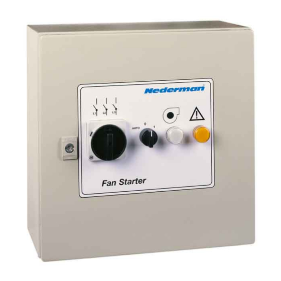
Compteur de temps de fonctionnement (50 Hz) 14372081 DESCRIPTION Le Fan Starter 5.5 sont des démarreurs direct pour ventilateurs NCF de Nederman. Le Fan Starter est équipé d’un interrupteur principal à 4 pôles verrouillé avec la porte afin qu’il soit impossible d’ouvrir la porte lorsque l’interrupteur est en position de marche. - Page 14 Fan Starter 5.5 FRANÇAIS équipement externe de 24 V CA. L’alimentation en 24 V CA peut être connectée en continu (borne 3-4) ou avec S1 en position « AUTO » (borne 111-112, non disponible si l’équipement est connecté au FilterMax).
-
Page 15: Montage
Fan Starter 5.5 FRANÇAIS MONTAGE Étudier attentivement ces instructions avant d’effectuer le montage. Le non-respect des avertissements et instructions indiqués risque d’entraîner dysfonctionnements ou dangers pour les individus. Avertissement ! Lire « Sécurité » à la page 12 avant de commencer le travail. - Page 36 Fan Starter 5.5 Spare parts When ordering parts always state: • Part No. and control no. (from the type label). • Detail No. of the spare part and the name (as per list below). • Quantity of parts required. Ersatzteile Bei der Bestellung von Ersatzteilen sind folgende Angaben zu machen: •...
- Page 39 Fan Starter 5.5...
- Page 40 Fan Starter 5.5 Fan Starter 4...
- Page 41 Fan Starter 4 Fan Starter 5.5...
- Page 43 Fan Starter 5.5 Fan Starter 4...
- Page 45 Fan Starter 5.5 FRANÇAIS /s. 39/ Schéma des circuits principaux 3/N/PE CA, 400/230 V, 50 Hz CA 24 V, TENSION DE COMMANDE FAN STARTER CA 24 V, ALIMENTATION VERS ÉQUIPEMENT EXTERNE CA 230 V, ALIMENTATION VERS ÉQUIPEMENT EXTERNE /s.40/ Schéma des circuits de commande CONTACTEUR PRINCIPAL VOYANT TÉMOIN D’ERREUR (SURCHARGE)