Table des Matières
Publicité
Les langues disponibles
Les langues disponibles
Liens rapides
Publicité
Chapitres
Table des Matières

Sommaire des Matières pour THOMSON VISION 1N
- Page 1 VISION 1N Gebrauchsanleitung Instruction manual Instructions de service...
-
Page 2: Table Des Matières
Inhaltsverzeichnis Vorwort....................3 Tastaturbelegung / Display ...............4 Horizontalbetrieb ..............5 Rotationsgeschwindigkeit ............5 Neigung ...................5 Neigung im manuellen Modus ..........7 Ausblend – Modus ..............7 Scan-Modus ................8 Einstellung der Nivellier-Empfindlichkeit (Windy) ....8 TILT-Funktion ................8 Stromversorgung – Laser ............9 Funk-Fernbedienung FB-V (Option) ........10 Empfänger ................11 TE 6 ..................12 TE 7 ..................13 Überprüfung der Justierung ..........14... -
Page 3: Vorwort
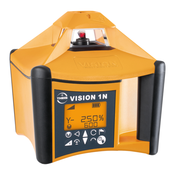
Gebrauchsanleitung Vorwort VISION 1N ...für den Profi am Bau. Der Rotationslaser THEIS VISION 1N setzt Maßstäbe im Bereich der vollautomatischen Profilaser. Er ist das Ergebnis langjähriger Erfahrung und innovativer Technik. Der qualitativ hochwertige Baulaser zeichnet sich durch Robustheit sowie höchster Präzision aus - Made in Germany - und sollte auf keiner Baustelle fehlen. -
Page 4: Tastaturbelegung / Display
Tastaturbelegung / Display Optisches Visier Laseraustritt - Rotation Akkufach Produktinfos (Rückseite) Via QR-Code u.a. Ladebuchse Gebrauchsanleitung Neigung Nivellier- Endanschlag , Batterie- Manueller anzeige Lageänderung anzeige Modus Y-Achs - Neigung Drehzahl oder Scan Windy Ausblenden Scan beenden Störung Neigung Linksdrehung Neigung Rechtsdrehung Ein/Aus Y-Achse... -
Page 5: Horizontalbetrieb
1. Horizontalbetrieb Stativ ausrichten und VISION mit Stativschraube fest anziehen. Die Ausrichtgenauigkeit beeinflusst die Größe des Neigungsbereichs. Mit Ein/Aus-Taste das Gerät einschalten. Es blinkt die Nivellieranzeige im beleuchteten Display. Falls der Stativkopf stärker als 5° geneigt ist, wird dies nach kurzer Zeit durch schnelles Blinken des Laser- strahls und des Alarm-Symbols angezeigt. - Page 6 2-ter Tastendruck: Y, Neigungsanzeige und 1. Ziffer Neigungswert blinken im Display. Neigungswert mit den Pfeiltasten einstellen. Die je- weils blinkende Ziffer kann verändert werden. Zur nächsten Stelle gelangt man mit den Tasten Links- /Rechtsdrehung. Für Änderung des Vorzeichens (±) die linke Taste verwenden. Plus wird nicht angezeigt. Bei lang anhaltendem Drücken der Pfeiltasten verän- dert sich der Wert mit zunehmender Beschleunigung.
-
Page 7: Neigung Im Manuellen Modus
4. Neigung im manuellen Modus Um beispielsweise größere Neigungen unter zu Hilfen- ahme eines Winkeltisches einstellen zu können, oder um bauseits vorgegebene Neigungen aufzunehmen, muss die Automatik des Gerätes ausgeschaltet werden. Dies geschieht durch langen Tastendruck der Ein-/Aus- Taste (ca. 5 Sek). Hinweis im Display durch blinkende Hand. -
Page 8: Scan-Modus
6. Scan-Modus Durch Drücken der Scan-Taste gelangt man in den Scan-Modus, mit der kleinsten Einstellung von 10°. Durch weiteres Drücken der Taste können 5 verschie- dene Größen einer Laserlinie erzeugt werden (10°, 20°, 40°, 60°, 80°); diese werden im Display angezeigt. Mit den Tasten Links-/Rechtsdrehung kann man die La- serlinie entsprechend verfahren. -
Page 9: Stromversorgung - Laser
9. Stromversorgung – Laser Die Kapazitätsanzeige des Akkus zeigt den Zustand des Akkus in 4 Stufen an. Wenn die 3 Balken in der Anzeige leer sind und der äu- ßere Rahmen blinkt, ist die Kapazität erschöpft und der Akku muss geladen werden. Wird dies nicht beachtet, schaltet das Gerät nach einiger Zeit automatisch ab. -
Page 10: Funk-Fernbedienung Fb-V (Option)
10. Funk-Fernbedienung FB-V (Option) Die Funk-Fernbedienung ist bidirektional konzipiert. Alle Informatio- nen die im Display des Lasers angezeigt werden, finden sich auch im beleuchteten Display der Fernbedienung wieder. Die Tastensym- bole auf dem Bedienfeld, entsprechen den Tasten auf der Lasertas- tatur. -
Page 11: Empfänger
Standby versetzen. Mit einer beliebigen Taste an der FB-V kann der Standby-Modus beendet werden und das Gerät kehrt in den Normalbetrieb zurück, wie nach dem erneuten Einschalten des Ge- rätes. Die maximale Standby-Zeit lässt sich im Info-Menü einstellen (siehe Kapitel 13). Wird die Standby-Zeit überschritten schaltet sich der Laser aus. - Page 12 TE 6 Anzeige Fein Grob Pfeil für Bewegungsrichtung Zentrum Balken Pfeil für Bewegungsrichtung Batterieanzeige Anzeige akustisches Signal LCD – Anzeige Sensorfenster (auch Rückseite) Kerbe Zentrum Taste Ein / Aus Taste Fein / Grob Taste bzw. Austritt akustisches Signal Batteriefach (Rückseite)
- Page 13 TE 7 Anzeige Grob Fein Pfeil für Bewegungsrichtung (Nähe Zentrum) Zentrum Balken (Nähe Zentrum) Pfeil für Bewegungsrichtung Anzeige akustisches Signal Batterieanzeige (3 Lautstärken) Austritt akustisches Sensorfenster Signal (Rückseite) Beleuchtete LCD – Anzeige (auch Rückseite) LED Richtungs- anzeige Kerbe Zentrum Zentrum LED Richtungs- anzeige Ein / Aus...
-
Page 14: Überprüfung Der Justierung
12. Überprüfung der Justierung Laser-Nivellier, wie unter 1. beschrieben (aber auf einem sehr gut ausgerichteten Stativ) aufbauen und entlang einer etwa 30 m langen Messstrecke – beispielsweise mit der X- Achse beginnend – ausrichten und einschalten. Am Ende der Messtrecke in Höhe des Laserstrahls eine Markierung vornehmen. - Page 15 US wählen (Achtung: Nur für USA und AUS) Speichern und nächster Menüpunkt % / ‰ - Einstellung Einstellung (% - Einstellung ist Standard) Speichern und nächster Menüpunkt Startdrehzahl wählen 600 oder 800 U/min einstellen Speichern und nächster Menüpunkt Lcdb Display Beleuchtungsdauer SEC.
- Page 16 Info und Einstellungen FB - V Zusammen drücken 144522 Seriennummer z.B. Nächster Menüpunkt build89 Software Version z.B. Nächster Menüpunkt CH5 EU Automatische Kanalwahl oder manuell einstellen. z.B. Kanal wählen 1 - 16 mit bestätigen. (Kanal CH Auto: Voreinstellung für automatische Wahl) US wählen (Achtung: Nur für USA und AUS) Speichern und nächster Menüpunkt...
-
Page 17: Lieferumfang
14. Lieferumfang Standard Option Laser Zielfernrohr Akku ( 4 Monozellen) Funkfernbedienung FB -V Netzgerät Empfänger Gebrauchsanleitung Stativ Schutzkasten 15. Betriebsanzeigen und Störungen Displayanzeige: Gerät zur Überprüfung an autorisierte Werkstatt oder direkt zum Hersteller schicken. 16. Garantie Wir gewährleisten für unsere Erzeugnisse eine dem heutigen Stand der Technik entsprechende Fehlerfreiheit in Material und Werkar- beit. -
Page 18: Kurzanleitung
17. Kurzanleitung Ein-/Ausschalten Manueller Modus (5 Sek. drücken) Drehzahl (U/min) 4 Stufen: 0 - 800 Verfahren des Laserstrahls (Schrittbetrieb) Neigung Anzeige letzte Eingabe Eingabe Y Bestätigung Ziffern - und Vorzeichenwahl Ausblendmodus Aktivierung 90 bis 270°: Deaktivierung Positionieren des Ausblendbereichs Scanmodus 5 Stufen, 10 bis 80°... -
Page 19: Technische Daten
18. Technische Daten Laser Laserklasse / High Power 2 / 3R Wellenlänge 635 - 660 nm Ausgangsleistung / High Power < 1mW / < 5mW Reichweiten Siehe Empfänger Selbstnivellierbereich ± 5° Nivelliergenauigkeit ± 1,5 mm / 30 m Neigungsgenauigkeit ± 0,1% bis 5% Neigung Neigung Y ±... -
Page 20: Lieferantenerklärung / Sicherheitshinweise
19. Lieferantenerklärung / Sicherheitshinweise Das Gerät erfüllt die Forderungen folgender Richtlinien: 2004/108/EG, RTTE 1999/5/EG sowie 2011/65/EU Zur Beurteilung des Erzeugnisses wurden folgende Normen herangezogen: EN 60950-1, EN 61000-6-3, EN301489-1, EN300220-1 V2.4.1, EN 61000-6-2, EN301489-3 und EN300220-2 V2.4.1 Sicherheits-Hinweisschild befindet sich auf der linken Seite des Gerätes Eingebaut ist ein gekapselter Laser Klasse 3R (3B bei High Power Version). -
Page 21: Entsorgung
Niemals in den Laser-Strahl blicken oder anderen Personen in die Augen leuchten! Dies gilt auch in größeren Abständen vom Gerät! Laser immer so aufstellen, dass Personen nicht in Augenhöhe angestrahlt werden (Achtung bei Reflexionen). 20. Entsorgung Vermessungsgerät, Zubehör und Verpackung sollten einer umwelt- gerechten Wiederverwertung zugeführt werden. - Page 22 Contents Introduction ..................23 Keyboard /Display ................24 Horizontal Operation .............25 Rotation - Speed ..............25 Slope ..................25 Slope in Manual Mode ............27 Mask Mode ................27 Scanning Mode ..............28 Setting the Levelling Sensitivity (Windy) .......28 TILT Function ................28 Power Supply of Laser ............29 Radio Remote Control FB-V (Option) ........30 Detector .................31 TE 6 ..................32...
-
Page 23: Introduction
Instruction manual Introduction VISION 1N ... for the construction professional. The rotation laser THEIS VISION 1N sets new standards in the ar- ea of fully automated professional lasers. It is the result of many years of experience and innovative technol- ogy. -
Page 24: Keyboard /Display
Keyboard /Display Optical sight Laser exit rotation Productinformation Via QR-Code on re- Battery compartment verse, e.g. Instruction manual Charging socket Slope Levelling End stop, Battery Manual display Position change display mode Y axis slope Windy Mask Disturbance Scan Speed or mode Scan-stop Counter clockwise... -
Page 25: Horizontal Operation
1. Horizontal Operation Align the tripod and screw the TPL tight using the tripod screw. The precision of alignment affects the size of the slope range. Use the On/Off switch to switch on the device. The levelling indicator flashes on the lit display. If the tripod head is sloping by more than 5°, this is indicated by the laser beam flashing quickly and the alarm symbol being displayed. - Page 26 2nd key press: Y, slope symbol and one digit of the slope value flashes on the display. Use the arrow keys to set the slope. The blinking digit can be changed. To select the digits you must press the counterclock- wise/clockwise rotation keys.
-
Page 27: Slope In Manual Mode
4. Slope in Manual Mode To be able to set higher grades using a level table or to record building-side specified grades, for example, you must switch off the device's automatic system. You do this by pressing the On/Off key for a long time (approx. -
Page 28: Scanning Mode
6. Scanning Mode You get to scanning mode by pressing the Scan key. It is possible to generate five different sizes of laser line. The scanning angle increases each time you press the Scan key again. The respective size of the laser line is shown on the display (10°, 20°, 40°, 60°, 80°) Using the counterclockwise/clockwise rotation keys, you can travers the laser line appropriately. -
Page 29: Power Supply Of Laser
9. Power Supply of Laser The battery level indicator shows the battery status in four steps. If the three bars on the display are blank and the outside frame flashes, the battery is flat and you must charge it. If you do not notice this, the device switches off automat- ically after a certain amount of time. -
Page 30: Radio Remote Control Fb-V (Option)
10. Radio Remote Control FB-V (Option) The wireless remote control is designed on a bidirectional basis. All the information that is shown on the laser's display can also be seen on the lit-up display of the remote control. The key symbols on the operator panel correspond to the keys on the laser keypad. -
Page 31: Detector
info-menu (see capital 13). The laser switches off if standby-period is exceeded. Power is supplied by two alkaline micro AAA batteries. The service life is approximately 60 hours. The battery symbol shows the status of the FB - V's batteries. To change the batteries, open the cover on the back and replace the batteries. - Page 32 TE 6 Display Fine Coarse Arrow for direction of movement Centre bar Arrow for direction of movement Battery display Display of audible signal Sensor window LCD display (on reverse too) Centre notch On/Off button Fine/Coarse button Button or issuing of audible signal Battery compartment (on reverse)
- Page 33 TE 7 Diplay Coarse Fine Arrow for direction of movement (Near centre bar) Centre bar (Near centre bar) Arrow for direction of movement Display of audible signal Battery display (3 stages) Issuing of audible Sensor window signal (on reverse) Illuminated LCD –...
-
Page 34: Calibration Check
12. Calibration Check Set up the laser leveller as described in point 1. (but on an extremely well aligned tripod) and align it along a traverse length of approximately 30 metres – starting with the X axis, for example – and switch it on. At the end of the traverse length, make a mark at the level of the laser beam. - Page 35 Select: US (Attention: Only for USA and AUS) Save and next menu item % / ‰ - setting % setting (% setting is default) ‰ - setting Save and next menu item Select start rotation speed Select 600 or 800 rpm Save and next menu item Lcdb Display of lighting timeout...
- Page 36 Information and settings FB – V Press buttons Serialnumber 144522 e.g. Next menu item Program Version .build 089 Next menu item Automatic channel selection or select manual. CH5 EU Select channel 1 - 16 and confirm (Channel CH Auto is for automatic selection.) Select US (Attention: Only for USA und AUS) Save and next menu item Battery voltage FB - V...
-
Page 37: Delivery Contents
14. Delivery Contents Standard Option Radio remote control FB – V Laser Rechargeable batteries Sighting telescope (4 Mono-cells) Detector Power supply unit Tripod Instruction Manual Protective case 15. Special Indications and Troubleshooting Displayed: Send the equipment for inspection only to an authorized service partner or directly to the manufacturer. -
Page 38: Brief Instructions
17. Brief instructions Switch on/off Manual mode (press for 5 sec.) Speed On/ Off 5 steps: 0 - 800 Traversing the laser beam (step mode) Slope Display of last input Input Y Confirmation Change sign and digits Mask mode Activation of 90 to 270°: Deactivation Positioning the mask area Scanning mode 5 steps 10 to 80°... -
Page 39: Technical Data
18. Technical Data Laser Laser Class / High Power 2 / 3R Wavelength 635 - 660 nm Output Power / High Power < 1mW / < 5mW Range See detector Self-levelling range ± 5° Levelling precision ± 1,5 mm / 30 m 3,4,5 Grade accuracy ±... -
Page 40: Supplier Declaration/Safety Information
19. Supplier Declaration/Safety Information The device complies with European Directives: 2004/108/EG, RTTE 1999/5/EG sowie 2011/65/EU Harmonized standards: EN 60950-1, EN 61000-6-3, EN301489-1, EN300220-1 V2.4.1, EN 61000-6-2, EN301489-3 and EN300220-2 V2.4.1 A safety information plate is on the left-hand side of the device An embedded Class 3R (3B with the High Power version) laser is installed. - Page 41 Note: This equipment has been tested and found to comply with the limits for a Class B digital device, pursuant to part 15 of the FCC Rules. These limits are designed to provide reasonable protection against harmful interference in a residential installation. This equipment generates, uses and can radiate radio frequency energy and, if not installed and used in accordance with the instructions, may cause harmful interference to radio communications.
-
Page 42: Disposal
20. Disposal The surveying device, its accessories and packaging should be recycled in an environmentally friendly way. EU countries only: Never put electrical tools in domestic refuse! In accordance with EU directive 2012/19/EC concerning Waste Electrical and Electronic Equipment and its transposition into national legislation, measuring equipment that can no longer be used must be collected separately and recycled in an environmentally friendly... - Page 43 Table des matières Avant-propos .................. 44 Affectation des touches / Ecran ............45 Fonctionnement horizontal ........... 46 Vitesse de rotation ..............46 Inclinaison ................46 Inclinaison en mode de fonctionnement manuel ....48 Mode « Masquage » ............. 48 Mode « Scan » ..............49 Réglage de la sensibilité...
-
Page 44: Avant-Propos
Avant-propos VISION 1N ... pour les professionnels de la construction. Le laser rotatif THEIS VISION 1N fixe une nouvelle référence dans le domaine des lasers de profil pleinement automatisés. Il résulte d'une longue expérience et de techniques novatrices. Le laser de construction de grande qualité se distingue par sa soli- dité... -
Page 45: Affectation Des Touches / Ecran
Affectation des touches / Ecran Viseur optique Sortie du rayon laser - Rotation Compartiment de l'accu Informations produit à l‘arrière via QR-Code, par Prise de ex. instructions de service chargement Butée finale, Affichage Statut de la Mode modification de Inclinaison du niveau batterie manuel... -
Page 46: Fonctionnement Horizontal
1. Fonctionnement horizontal Aligner le trépied et fixer le VISION au moyen de la vis du trépied. La précision d'alignement influence la grandeur de la plage d'inclinaison. Démarrer l'appareil au moyen de la touche Marche/Arrêt. L'affichage du niveau clignote dans l'écran éclairé. Une inclinaison de la tête du trépied supérieure à... - Page 47 2ème pression sur la touche : Y, valeur d'inclinaison et la ère chiffre de la valeur d'inclinaison clignotent à l'écran. Régler la valeur d'inclinaison à l'aide des touches fléchées. Vous pouvez régler chaque chiffre clignotant. Utiliser les touches rotations à gauche / droite pour accé- der au point suivant.
-
Page 48: Inclinaison En Mode De Fonctionnement Manuel
4. Inclinaison en mode de fonctionne- ment manuel Pour, par exemple, pouvoir réglée des plus grandes inclinaisons au moyen d’une table rectangulaire, le système automatique de l’appareil doit être désactivé. Ceci se fait en maintenant la touche Marche/Arrêt enfoncée (env. 5 sec.). Indication à l'écran par une main clignotante.. Aligner alors tout d'abord le laser précisément sur la cible au moyen de la lunette de visée ou du viseur optique, puis indiquer l'inclinaison:... -
Page 49: Mode « Scan
6. Mode « Scan » Un appui sur la touche Scan permet d'accéder au mode Scan au réglage le plus petit de 10°. Des appuis supplé- mentaires sur la touche permettent de générer 5 dimen- sions différentes de ligne laser (10°, 20°, 40°, 60°, 80°) ; elles sont affichées à... -
Page 50: Alimentation En Courant - Laser
9. Alimentation en courant – Laser L'affichage de capacité de l'accu indique l'état de l'accumulateur sur 4 niveaux. Lorsque les 3 barres de l'affichage sont vides et le cadre extérieur clignote, la capacité est épuisée et l'accu doit être chargé. Si ce n’est pas le cas, l’appareil s’arrête automatiquement après un certain temps. -
Page 51: Télécommande Radio Fb-V (Option)
10. Télécommande radio FB-V (option) La télécommande radio est conçue de manière bidirectionnelle. Toutes les informations s'affichant à l'écran du laser apparaissent également sur l'écran éclairé de la télécommande. Les symboles des touches sur le champ de commande correspondent aux touches sur le clavier du laser. -
Page 52: Récepteur
quelle touche de la télécommande et l’appareil reprend son fonctionnement normal, comme après sa remise sous tension. La durée maximum de veille peut être réglée dans le menu info (voir chapitre 13). Si le temps d'attente est dépassé, le laser s'éteint. L'alimentation en courant se fait au moyen de deux piles alcalines Micro AAA. - Page 53 TE 6 Affichage Grossier Flèche pour le sens du mouvement Barre centrale Flèche pour le sens du mouvement Indicateur de l'accu Indicateur du signal acoustique Fenêtre de la sonde Affichage LCD (également à l’ arrière) Centre de l'encoche Touche Marche/Arrêt Touche Fin / Grossier Touche ou sortie du signal acoustique...
- Page 54 TE 7 Affichage Grossier Flèche pour le sens du mouvement (A proximité du centre) Barre centrale (A proximité du centre) Flèche pour le sens du mouvement Indicateur du signal Indicateur de la batterie acoustique (3 niveau) Sortie du signal Fenêtre de la sonde acoustique à...
-
Page 55: Vérification De L'ajustage
12. Vérification de l’ajustage Installer le niveau laser comme décrit au point 1 (mais sur un trépied très bien aligné), l'ajuster sur une distance de mesure d'environ 30 m – par exemple en commençant par l'axe X – et l'allumer. Effectuer un marquage à... - Page 56 Sélectionner US (Attention: seulement pour USA et AUS) Enregistrer et point suivant du menu Réglage % / ‰ Réglage % (le réglage % est le réglage par défaut) ‰ - Réglage Enregistrer et point suivant du menu Sélectionner le départ de régime Sélectionner 600 ou 800 tr/min Enregistrer et point suivant du menu Lcdb...
- Page 57 Information et réglages FB- V Enfoncer les touches Numéro de fabrication 144522 par ex. Point suivant du menu Version de programme build 089 par ex. Point suivant du menu Sélection automatique du canal ou réglage manuel CH5 EU par ex. Choix du canal: 1 –...
-
Page 58: Contenu De La Livraison
14. Contenu de la livraison Standard En option Laser Lunette de visée Télécommande radio FB – V Accu (4 piles) Chargeur Récepteur Instructions de service Trépied Coffret de protection 15. Affichages de statut et perturbations Affichage à l'écran: Renvoyer l'appareil pour contrôle à un atelier agréé ou directement au fabricant. -
Page 59: Instructions Succinctes
17. Instructions succinctes Allumer / Arrêter Mode manuel (appuyer pendant 5 sec.) Régime (tr/min.) 4 niveaux : 0 - 800 Déplacement du rayon laser (régime pas-à- pas) Inclinaison Affichage de la dernière valeur Valeur X Confirmation Sélection de chiffres et de signes Mode <... -
Page 60: Caractéristiques Techniques
18. Caractéristiques techniques Laser Classe de laser / High Power 2 / 3R Longueur d’onde 635 - 660 nm Puissance de sortie / High Power < 1mW / < 5mW Portées Cf. récepteur Plage de nivelage autom. ± 5° Précision du niveau ±... -
Page 61: Déclaration Du Fournisseur / Consignes De Sécurité
19. Déclaration du fournisseur / Consignes de sécurité Cet appareil est conforme aux prescriptions européennes : 2004/108/EG, RTTE 1999/5/EG sowie 2011/65/EU L'attestation se base sur les normes harmonisées : EN 60950-1, EN 61000-6-3, EN301489-1, EN300220-1 V2.4.1, EN 61000-6-2, EN301489-3 et EN300220-2 V2.4.1 La plaquette portant les consignes de sécurité... -
Page 62: Elimination
Toujours placer le laser de sorte que le rayon ne se trouve pas à hauteur des yeux des personnes présentes (attention aux angles de réflexion). 20. Elimination Les appareils de mesure, accessoires et emballages doivent être recyclés dans le respect de l’environnement. Uniquement pour les pays de l’Union Européenne : Ne pas jeter les outils électriques dans les ordures ménagères! - Page 64 Laserwarnschild für VISION Laser warning label for VISION Signal de danger « Laser » pour VISION Laserwarnschild für VISION High Power Laser warning label for VISION High Power Signal de danger « Laser » pour VISION High Power Änderungen vorbehalten Subject to changes Sous réserves de modifications THEIS FEINWERKTECHNIK GMBH...