Publicité
Liens rapides
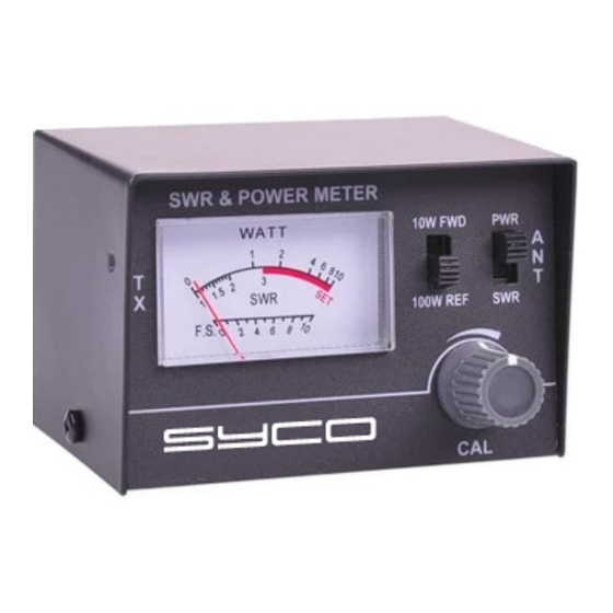
SWR - POWER METER
EN
Meter for checking SWR everytime an aerial is moved or
a new one installed to ensure maximum range and signal
strength.
• SWR / PWR Meter
• 26.MHz – 30MHz
• RF Power: 0-10W / 10-100W
• Connector SO239
• Precision 5%
• 85 x 56 x 60mm
The SWR Function of the test instrument is probably the most useful test performed. Testing for the SWR of Standing Wave Radio
provides the operator of the transmitter a good indication of the condition of his antenna and antenna lead cable since most antennas
are located externally of the transmitter. In order to get the maximum amount of power radiated from the antenna, the lead line or coax
and the antenna should be matched to the transmitter. For this meter a 52ohm match is required which includes most CB operations
that use RG-58U or RG-8U coax. Because a perfect match is never achieved the amount of mismatch can be measured by measur-
ing the amount of Standing Waves that exist in the coax or antenna feed-line. Measuring the Standing Waves can be accomplished by
sampling the Forward "FWD" power and the reflected "REF" power and comparing them and then expressing this difference as a ratio
of reflected power to forward power. The following ratios are examples of the amount of power loss for a Standing Wave Radio.
POWER LOSS
0%
=
2%
=
3%
=
6%
=
A ratio of 1.1:1 to a 2:1 is usually considered satisfactory for most operations
OPERATION INSTRUCTION
1.
With your transceiver turned off, Connect
coaxial cable form transceiver to "TX" of
SWR meter and also connect antenna
cable "ANT" of SWR meter.
2.
To measure RF POWER set function
switch tot he "POW" position on 10 or 100
watts. Switch on the CB unit to transmit.
Read power in watts directly from the
lower meter scale.
3.
To measure SWR set function switch tot
he "FWD" position. Switch on the CB unit
to transmit. Adjust "CAL" control to achieve
a full scale reading at the "SET" mark.
4.
Set function switch tot he "REF" position.
Now the reflected power will be indicated
in SWR ratio from the top scale of the
meter. Always try to tone your antenna to
a minimum meter deflection in the "REF"
position.
CAUTION ON HANDLING
1.
Under output power of transmitter "ON",
don't take off coaxial cable running to an-
tenna. Extraordinary voltage may happenly
damage the transceiver.
2.
Don't give excessive shock on meter,
Because meter is integrated with high
sensitive meter.
SWR
POWER LOSS
1:1
11%
1.3:1
25%
1.5:1
38%
1.7:1
48%
70%
BEDIENUNGSANWEISUNGEN
1.
Koaxialkabel des Transceivers bei ausge-
schaltetem Gerat an "TX" Buchse sowie
Antennenkabel an "ANT" Buchse des
SWR Messgerates anschliessen.
2.
Zur Messung der RF Leisttung bitte den
Funktionsschalter auf "POW" stellen auf
10 oder 100 watss und den schalter des
CB Gerates in Sendeposition bringen,
woraufhin die Leistung von der unteren
Skala des Messgerates in Watt direkt
ablesbar ist.
3.
Zur Messung des Stehwellenverhaltnisses
bitte den Funktionsschalter auf "FWD"
stellen. Den Schalter des CB Gerates
in Sendeposition bringen un den "CAL"
Regler so einstellen, dass bel Markierung
"SET' eine Skalenendwertablesung er-
reicht wird.
4.
Funktionsschalter auf "REF"' stellen. Die
reflektierte Leistung wird nun als Ste-
hwellenverhaltnis auf der oberen Skala
des Messgerates angezeigt. Bite stets
versuchen, die Antenne so abzustimmen,
dess bei "REF" Einstellung ein minimaler
Zeigerausschlag des Messgerates erfolgt.
Wamhinweise
1.
Bei eingeschaltetem Sender das zur
Antenne fuhrende Koaxialkabel nicht tren-
nen, da ansonsten der Transceiver durch
die ausserodentliche Spannung schaden
nehmen konnte.
2.
Messgerat bitte keiner ubermassigen Er-
schutterung aussetzen, da das integrierte
instrument ausserstempfindlich ist.
SWR
=
2:1
=
3:1
=
4:1
=
5:1
=
10:1
MODE D'EMPLOI
•
•
•
•
ATTENTION
1.
2.
Brancher votre TOSMETTRE WATT-
METRE entre votre émetteur CITIZEN
BAND et votre antenne CB à l'aide d'un
cordon avec 2 PL 259 référence NC 535.
L'émetteur doit être branché du côté de
l'inscription "TX" et l'antenne du côté
"ANT".
Pour mesurer la puissance de sortie de
votre émetteur, positionner l'interrupteur
vers 'POW" sur l'échelle 10 ou 100 watts,
ensuite mettre en marche votre CB et
émettre. La lecture de la puissance se fait
sur l'échelle basse du vu-mêtre graduée
en WATTS.
Pour mesurer le taux d'onde stationnaire
de votre antenne: Positionner l'interrupteur
vers "FWD" ensuite mettre en marche
votre CB et passer en mode émission, et
simultanément ajuster le bouton de cali-
brage "CAL" de manière à ce que l'aiguille
du vu-métre soit exactement sur le repère
"SET" situé en fin de l'échelle "SWR".
Positionner l'interrupteur vers REF et
passer de nouveau en émission. Le
taux d'onde stationnaire ou la puissance
réfléchie par votre antenne est maintenant
indiqué sur l'échelle "SWR" du vu-mètre. Il
faut dans tous les cas, que le taux d'onde
stationnaire soit le plus bas possible, c'est
à dire le plus près de 1.1.
Ne pas émettre quand le câble coaxial
de votre antenne est débranché, cela
détériorerait les transistors HF de votre
émetteur.
Ne pas faire subir de chocs à votre
TOSMETTRE WATMETTRE le vu-métre
intégré étant d'une très haute sensibilité.
Publicité

Sommaire des Matières pour Syco JX-20
- Page 1 SWR - POWER METER Meter for checking SWR everytime an aerial is moved or a new one installed to ensure maximum range and signal strength. • SWR / PWR Meter • 26.MHz – 30MHz • RF Power: 0-10W / 10-100W • Connector SO239 • Precision 5% • 85 x 56 x 60mm The SWR Function of the test instrument is probably the most useful test performed.
- Page 2 H A N D L E I D I N G M O D E D ’ E M P L O I U S E R M A N U A L SWR - POWER METER MODEL JX-20 4 SET Kenmerken: • Impedantie : 50 Ohm •...