Chapitres

Sommaire des Matières pour Cassese MF 20
- Page 1 MF 20 AIR OPERATED HANGER FIXER SERTISSEUSE PNEUMATIQUE TECHNICAL AND USER MANUAL MANUEL TECHNIQUE ET D’ UTILISATION Version 3 au 06 / 2007 Valid from machine S/N - Depuis la machine N° Cassese / Communication...
- Page 2 4 8 5 8 5 ! " #$ !& #$ ' ) # * ! * ! * +#$, ! $$ ,$ ! 7 "/ ,$ ! $ "/ ,$ ! 7 1"/ ,$ ! $ 1"/ :: ;. - + $ <...
- Page 3 Z5805 Réglet 0-100 Réglet 0-100 Z5806 Réglet 0-245 Réglet 0-245 Z6320 Vis TBHC M6-16 à embase ULF -10.9 ScrewTBHCULFM6-16 Z6410 Profil alu Lg 490 Alu profile Lenght 490 Z667 VisFHCM6-12-8.8 ScrewFHCM6-12 Z669 VisFHCM6-16-8.8 Screw FHC M6-16 Z670 Vis FHC M6-20 - 8.8 Screw FHC M6-20 Z678 Connection maie 1/4...
- Page 10 OTHERS CASSESE MULTIFIX MACHINES TO FIX SPECIAL* HANGERS & STRUT- BACK HINGES Model Description Consumption Weight Dimensions MF10 FOOT OPERATED MACHINE 32 KG (71 LBS) 800 X 600 X1250 MM 32” X 24” X 50” MF30 AUTOMATIC, COIL - FED...
-
Page 11: Table Des Matières
SPECIFICATIONS / GUARANTEE OPTIONS PUTTING INTO OPERATIONS UNPACKING SETTING-UP ADJUSTMENTS SETTING DISTANCE OF HANGER FROM TOP SETTING CENTER OF LONG/SHORT DIMENSIONS INSTALLING THE BOTTOM STAMP FOR HANGERS USE OF POSITION STOPS FIXING HANGERS MAINTENANCE PREVENTIVE MAINTENANCE MF 20 04 / 2001... -
Page 12: Introduction
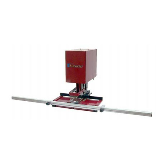
You have just bought a Cassese machine Multifix MF20. We congratulate on your sensible choice and thank you for your trust in Cassese products. The MF20 benefits from the experience of picture framing equipment that brought Cassese a certain reputation. The MF20 is designed to fix special no-screw-no-nail hangers on the backboards of the frames. - Page 14 MF 20 Advised way of fitting : AIR LINE FITTINGS STANDARD Male Connector on Machine Z 678 Z 678 quick release (Q/R) female air connector Z 749 Q/R US male Standard hose connector connector Z 701 Z 556 AIR SOURCE (compressor)
- Page 15 Remove the 3 screws with a 19-mm flat spanner. and remove it upwards. Place the MF 20 on a work table, tilt it on its side and fit the 3 feet, placing a washer under each nut. Engage the left joint plate...
-
Page 16: Setting Distance Of Hanger From Top
ADJUSTMENTS Example: At 3 cm from the top of the backboard, fixing of 2 hangers # 1428. Backboard dimensions : 20 x 30 cm. 1) SETTING DISTANCE OF HANGER FROM TOP OF BACKBOARD 3 cm Slide backstop BP to reach 3 cm on Loosen the 2 handles MP that fix the position of back- the scales underneath and tighten the stops BP. -
Page 17: Use Of Position Stops
SAFETY: The front plexi protection cover is part of the safety system of your Cassese MF20. It is forbidden to remove it and to use the machine without the safety cover. The presser head that carries out the fixing of hangers is connected to the safety cover. When the safety cover is open more than 8 mm (5/16”) from the machine’s work bench, the presser head is prevented... -
Page 18: Preventive Maintenance
MAINTENANCE BEFORE ANY TECHNICAL INTERVENTION, MAKE SURE THE MACHINE IS DISCONNECTED FROM THE COMPRESSED AIR SOURCE. PREVENTIVE MAINTENANCE Lubrication: it is advised to open the machine’s main frame to grease once every six months these 2 articulations. -
Page 19: Mf 20 - Manuel Technique & D' Utilisation
MF 20 - MANUEL TECHNIQUE & D’ UTILISATION SOMMAIRE N° PAGE INTRODUCTION ACCESSOIRES FOURNIS AVEC LA MACHINE SPECIFICATIONS TECHNIQUES OPTIONS GARANTIE MISE EN SERVICE DEBALLAGE , MONTAGE REGLAGES REGLAGE DE LA PROFONDEUR DE POSE REGLAGE DU CENTRAGE LONGUEUR / LARGEUR MISE EN PLACE DE L’ENCLUME ET DE L’ATTACHE... -
Page 20: Introduction
INTRODUCTION Vous venez d’acquérir une MF 20. Nous vous félicitons pour votre bon choix et vous remercions pour votre confiance. La MF20 bénéficie de l’expérience des sertisseuses qui ont fait la notoriété de Cassese. La MF20 permet la pose des attaches dos de cadre . -
Page 21: Raccordement Pneumatique
MF 20 RACCORDEMENT PNEUMATIQUE STANDARD DETENDEUR MF 20 Z 678 Z 678 RACCORD RAPIDE FEMELLE Z 749 EMBOUT EMBOUT USA CANNELE Z 701 Z 556 COMPRESSEUR... - Page 22 AVANT Couper avec un cutter les La MF 20 est fixée avec 3 vis A, B, C, situées sous la palette.Relevez la 2 sangles retenant le haut palette soutenant la MF20 avec des cales. Otez les 3 vis avec une clé...
-
Page 23: Reglage De La Profondeur De Pose
REGLAGES Exemple: Pose à 3cm de profondeur de 2 attaches 1428 sur un dos de cadre de dimensions: 20 x 30 cm. 1) REGLAGE DE LA PROFONDEUR DE POSE 3 cm Amenez BP sur la mesure 3 cm des 2 Desserez les 2 manettes MP de la barre de profondeur BP. -
Page 24: Utilisation Des Butees
EXECUTION SECURITE : Le capot est un élément de sécurité essentiel. Il est formellement interdit de le démonter et d’utiliser la machine sans celui-ci. La came qui lui est associée déclenche le sertissage, quand il ne subsiste que 8mm d’ouverture entre la table et le capot. Ce qui à pour effet d’empécher le déclenchement du sertissage si la main de l’opérateur se trouve sous le capot. -
Page 25: Entretien Preventif
MAINTENANCE AVANT TOUTES INTERVENTIONS DECONNECTER L’ ARRIVEE D’AIR . 1) ENTRETIEN PREVENTIF Graissage: 1 fois tous les 6 mois. - Page 26 Fax : 33 - 1- 64 - 06 - 04 - 19 33 - 1- 64 - 42 - 49 - 72 33 - 1- 64 - 49 - 58 - 94 WebSite : www.cassese.com E-mail : Cassese.xp@cassese.com SERVICE APRES VENTE / AFTER SALES DEPARTMENT / KUNDENDIENST DIENST / SERVICIO TÉCNICO: (33)-01-64-06-24-51 sav@cassese.com...


