
Manuels Connexes pour Opus Technologies OP-FSM

Sommaire des Matières pour Opus Technologies OP-FSM
- Page 1 Proximity amplifier- Proximity amplifier MESUREUR DE CHAMPS FIELD STRENGHT METER Manuel d’installation et d’utilisation OP-FSM Installation and user manual OP-FSM...
- Page 2 Manuel d'utilisation - User Manual...
- Page 3 Manuel d'utilisation - User Manual...
-
Page 4: Table Des Matières
1.4 Icônes 1.4.1 Icônes et notes 2. Description 2.1 La gamme 2.2 Le contenu 2.3 OP-FSM 2.4 Conseil et sécurité 3. Commandes, connexions et réglages 3.1 synoptique des raccords et des éléments de commande 3.1 Fonctions de mesure 3.3 Déroulement de la mesure 4. - Page 5 1.3 Alert 1.4 Icons 1.4.1 Icons and notes 2. Description 2.1 The range 2.2 Contents 2.3 OP-FSM 2.4 Safety notes 3. Connections and settings 3.1 Overview of the connection jacks ans operating elements 3.2 Measurement functions 3.3 Using the meter 4.
- Page 6 Manuel d’installation et d’utilisation OP-FSM Manuel d'utilisation - User Manual...
-
Page 7: Introduction
Introduction 1.4.1 Icônes et notes Merci d’avoir acheté la série d’amplificateur de boucle à induction Opus Technologies, s’il vous plaît prenez quelques instants pour lire cette notice, cela Les icônes utilisées avec les notes fournissent un vous assurera une utilisation optimale du produit et complément d'informations sur la note. -
Page 8: Le Contenu
2.1 Description • Un mesureur de champ OP-FSM • CD restituant les différents signaux tests L’OP-FSM est une solution idéale pour mesurer, sinusoïdaux de 100Hz à 6KHz. régler et mettre en service un système à boucle • La notice d’installation à... -
Page 9: Synoptique Des Raccords Et Des Éléments De Commande
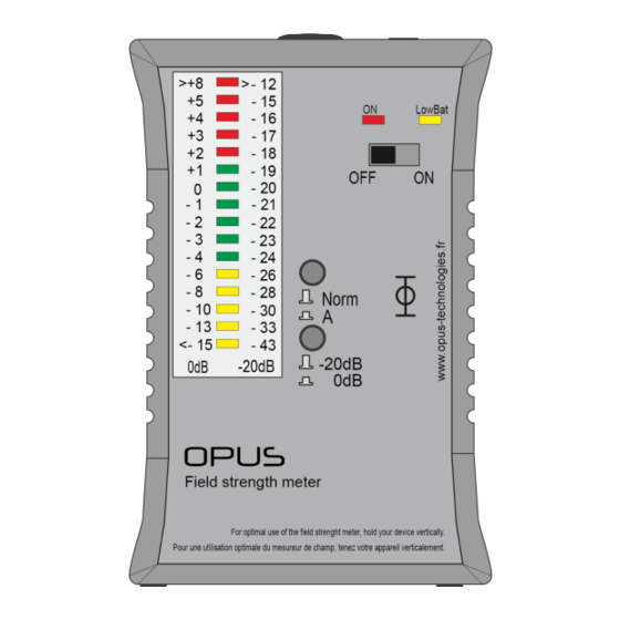
3. Commandes et réglages 3.1 Synoptique des raccords et des éléments de commande 1. Indication de l’intensité du champ, différenciation par couleur 2. Affichage marche/arrêt 3. Indicateur de pile usée 4. Interrupteur marche/arrêt 5. Sélecteur de filtre 6. Raccord écouteur 7. -
Page 10: Fonctions De Mesure
(habituellement au milieu de la boucle magnétique posée). Maintenir le OP-FSM à la verticale tout le long de l’opération. Respecter également la distance entre le sol et le mesureur, celle-ci dépendra de l’application de la boucle. - Page 11 4. Commandes, connexions et réglages Utiliser le CD fourni avec les signaux de référence et suivre les instructions suivantes pour adapter au mieux la boucle magnétique. Afin d’obtenir des mesures précises, toujours maintenir le OP-FSM à la verticale. Sélecteurs de la Valeurs de...
-
Page 12: Maintenance Et Entretien
5. Maintenance et entretien Élimination appareils électriques Il n’y a pas de maintenance sur le OP-FSM. S’il électroniques (dans les pays de l’Union est sale, nettoyer l’appareil avec un chiffon doux Européenne et dans les autres pays européens et légérement humidifié. N’utilisez jamais disposant d’un système de collecte distinct pour... -
Page 13: Alimentation Électrique
6. Caractéristiques techniques Étalonnage de l’échelle Mode de fonctionnement -20dB -20dB = 0,043A/m Mode de fonctionnement 0dB 0dB= 0,4A/m Type de mesure True RMS 125ms Réponse en fréquences Filtre A/Flat 30Hz...500Hz -3dB...-4dB 500Hz...2500Hz +/- 0,25dB 2500Hz...10KHz +/-3dB Sorties Écran LED de différentes couleurs Écouteurs Fiche de 3,5mm Alimentation électrique... - Page 14 Manuel d'utilisation - User Manual...
- Page 15 Installation and user manual OP-FSM Manuel d'utilisation - User Manual...
-
Page 16: Introduction
1.4 Icons 1. Introduction 1.4.1 Icons and notes 1.1 Purpose The Installation and Operation Manual provides the Icons used with notes provide additional infor- necessary information for installing, configu- ring mation about it. See the following examples: and using an DCL10-K kit. 1.2 Targeted audience Note: General icon of notes... - Page 17 Do not put the meter in contact with water. Using a headset, the OP-FSM allows you to listen Infiltration of water in the case can damage the to and control the installation of your magnetic electrical components that compose it.
-
Page 18: Overview Of The Connection Jacks Ans Operating Elements
3. Controls and settings 3.1 Overviex of the connection jacks and operating elements 1. Color-coded display of the field strength 2. On/Off indicator 3. Battery-low indicator 4. On/off switch 5. Filter selection switch 6. Measurement range selection switch 7. Headphone jack Switch setting for 8. -
Page 19: Measurement Functions
(usually in the middle of the magnetic loop being placed). Keep the OP-FSM upright throughout the operation. Respect also the distance between the ground and the meter, it will depend on the application of the loop. -
Page 20: Step-By-Step Instructions
Use the CD with the reference signal that is enclosed with the device and perform the following steps to perfectly adjust the loop to your needs. To ensure exact measurements, always hold the OP-FSM perpendicular to the floor. Measurement Signal... -
Page 21: Maintenance And Care
5. Maintenance and care Elimination electrical electronic There is no maintenance on the OP-FSM. If it is equipment (in European Union countries and in dirty, clean the unit with a soft, slightly damp other European countries with a separate cloth. Never use spirits, thinner or other organic collection system for this class of waste). - Page 22 6. Specifications Scale calibration Operating mode-20dB -20dB = 0,043A/m Operating mode 0dB 0dB= 0,4A/m Type of measurement True RMS 125ms Frequency response Filter A/Flat 30Hz...500Hz -3dB...-4dB 500Hz...2500Hz +/- 0,25dB 2500Hz...10KHz +/-3dB Outputs Display Color-coded LED dot display Headphones 3,5mm cinch Power supply Batteries 2xAA...
- Page 23 Manuel d'utilisation - User Manual...
- Page 24 Pour toutes questions complémentaires, contacter nous. For any questions, contact us. OPUS TECHNOL£OGIES — ZI Lagrange II — 9 Chemin de la Vieille Ferme — 33650 MARTILLAC Tel: (+33)09.81.24.00/06. — Fax: (+33)09.82.63.22.56. — contact@opus-technologies.fr 02/2018 Manuel d'utilisation - User Manual...