Table des Matières
Publicité
Les langues disponibles
Les langues disponibles
Liens rapides
OHIO SEMITRONICS, INC.
4242 Reynolds Drive
Hilliard, Ohio 43026
Telephone: 614-777-1005
Toll Free:
800-537-6732
FAX:
614-777-4511
e-mail:
info@ohiosemitronics.com
www.ohiosemitronics.com
Betriebsanleitung
Messumformer für Wechselspannung DVTR-XXXX
Mode d'emploi
Convertisseur de mesure
pour tension alternative DVTR-XXXX
Operating Instructions
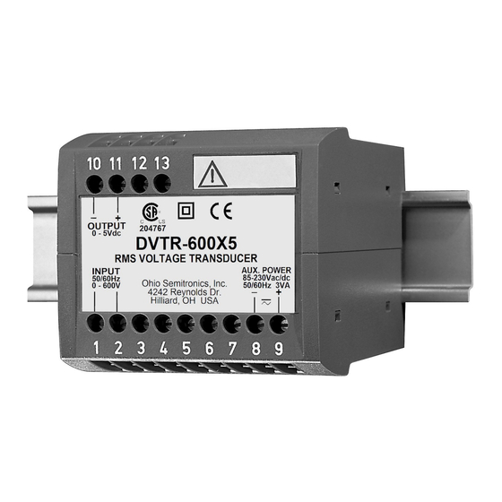
Transducer for AC voltage DVTR-XXXX
7004-00065-A
Rev --
Aug 12, 2009
Publicité
Chapitres
Table des Matières

Sommaire des Matières pour OHIO SEMITRONICS DVTR Série
- Page 1 Messumformer für Wechselspannung DVTR-XXXX Mode d’emploi Convertisseur de mesure pour tension alternative DVTR-XXXX Operating Instructions Transducer for AC voltage DVTR-XXXX 7004-00065-A Rev -- Aug 12, 2009 OHIO SEMITRONICS, INC. 4242 Reynolds Drive Hilliard, Ohio 43026 Telephone: 614-777-1005 Toll Free: 800-537-6732 FAX: 614-777-4511 e-mail: info@ohiosemitronics.com...
- Page 2 Betriebsanleitung Messumformer für Wechselspannung DVTR-XXXX ........3 Mode d’emploi Convertisseur de mesure pour tension alternative DVTR-XXXX ....6 Operating Instructions Transducer for AC voltage DVTR-XXXX ............9 Geräte dürfen nur fachgerecht entsorgt werden! Les appareils ne peuvent être éliminés que de façon appropriée! The instruments must only be disposed of in the correct way! 7004-00065-A Rev --.indd Page 2 of 12...
-
Page 3: Table Des Matières
Betriebsanleitung Messumformer für Wechselspannung DVTR-XXXX Messausgang Sicherheitshinweise, die unbedingt beachtet werden Gleichstrom: 0(0,2) - 1 bis 0(4) - 20 mA müssen, sind in dieser Betriebsanleitung mit folgenden Bürdenspannung: 15 V Symbolen markiert: 15 V Aussenwiderstand: max. [kΩ] ≤ [mA] = Ausgangsstromendwert Gleichspannung: 0(0,2) - 1 bis 0(2) - 10 V Aussenwiderstand:... -
Page 4: Befestigung
4. Befestigung – + Die Befestigung des DVTR-XXXX erfolgt auf einer Hutschiene. – + – Bei der Bestimmung des Montageortes müs- sen die «Umgebungsbedingungen», Abschnitt «3. Tech nische Daten», eingehalten werden! 12 13 12 13 Gehäuse auf Hutschiene (EN 50 022) aufschnappen (siehe Bild 1). -
Page 5: Inbetriebnahme Und Wartung
6. Inbetriebnahme und Wartung 9. Mass-Skizze Hilfsenergie und Messeingang einschalten. Es besteht die 112,5 Möglichkeit, während des Betriebes die Ausgangsleitung zu unterbrechen und ein Kontrollgerät anzuschliessen, z.B. für eine Funktions prüfung. 12 13 Der Messumformer ist wartungsfrei. 7. Demontage-Hinweis Messumformer gemäss Bild 7 von Tragschiene abnehmen. 114,1 Bild 8. -
Page 6: Description Brève
Mode d’emploi Convertisseur de mesure pour tension alternative DVTR-XXXX Sortie de mesure Les conseils de sécurité qui doivent impérativement Courant continu: 0(0,2) - 1 à 0(4) - 20 mA être observés sont marqués des symboles ci-contre Tension de charge: 15 V dans le présent mode d’emploi: 15 V Résistance extérieure:... -
Page 7: Fixation
4. Fixation – + Les DVTR-XXXX peuvent être montés sur des rails «à cha- peau». – + – En déterminant l’emplacement de montage, il faut tenir compte des indications fournis sous 12 13 12 13 la rubrique «Ambiance extérieure» du chapitre «3. -
Page 8: Mise En Service Et Entretien
6. Mise en service et entretien 9. Croquis d’encombrement Enclencher l’alimentation auxiliaire et l’entrée de mesure. 112,5 Il est possible d’interrompre le circuit de sortie pendant le fonctionnement pour brancher par exemple un appareil de contrôle. 12 13 Le convertisseur de mesure ne nécessite pas d’entretien. 7. -
Page 9: Brief Description
Operating Instructions Transducer for AC voltage DVTR-XXXX Measuring output Safety precautions to be strictly observed are marked DC current: 0(0.2) - 1 to 0(4) - 20 mA with following symbols in the Operating Instructions: Burden voltage: 15 V 15 V External resistance: max. -
Page 10: Mounting
4. Mounting – + The DVTR-XXXX can be mounted on a top-hat rail. – + – Note “Environmental conditions” in Section “3. Technical data” when determining the place of installation! 12 13 12 13 Simply clip the device onto the top-hat rail (EN 50 022) (see Fig. -
Page 11: Commissioning And Maintenance
6. Commissioning and maintenance 9. Dimensional drawing Switch on the power supply and the measuring input. It is 112.5 possible during the operation to disconnect the output line and to connect a check instrument, e.g. for a functional test. 12 13 No maintenance is required. -
Page 12: Declaration Of Conformity
10. Konformitätserklärung / Certificat de conformité / Declaration of conformity DVTR-XXXX EG - KONFORMITÄTSERKLÄRUNG EC DECLARATION OF CONFORMITY D o k u m e n t - N r . / U 5 5 3 . D O C D o c u m e n t . N o . : H e r s t e l l e r / C a m i l l e B a u e r A G M a n u f a c t u r e r :...