Table des Matières
Publicité
Les langues disponibles
Les langues disponibles
Liens rapides
Operating Instructions
<Installation Guide>
Installation Instructions provided
Center Module
WX-CC411
Model No.
WX-CC412
Before attempting to connect or operate this product,
please read these instructions carefully and save this manual for future use.
No model number suffix is shown in this Operating Instructions.
Publicité
Chapitres
Table des Matières
Dépannage

Manuels Connexes pour Panasonic WX-CC411


Sommaire des Matières pour Panasonic WX-CC411
- Page 1 Operating Instructions <Installation Guide> Installation Instructions provided Center Module WX-CC411 Model No. WX-CC412 Before attempting to connect or operate this product, please read these instructions carefully and save this manual for future use. No model number suffix is shown in this Operating Instructions.
-
Page 2: Safety Precautions
ENGLISH VERSION Safety precautions FEDERAL COMMUNICATIONS COMMISSION INTERFERENCE STATEMENT This equipment has been tested and found to comply with the limits for a Class A digital device, pursuant to part 15 of the FCC Rules. These limits are designed to provide reasonable protection against harmful interference when the equipment is operated in a commercial environment. -
Page 3: Important Safety Instructions
Safety precautions For U.S.A. CAUTION: The model number and serial number of this product may Danger of explosion if battery is incorrectly replaced. be found on the surface of the unit. Replace only with the same or equivalent type. You should note the model number and serial number of These servicing instructions are for use by qualified this unit in the space provided and retain this book as a service personnel only. -
Page 4: Table Des Matières
Contents Safety precautions ............2 Screen operations ............29 Basic screen operations ..........29 Before use ................. 5 Entering the settings ............ 29 Preface ................5 Inputting characters ............. 30 Features ................. 5 Inputting the date and time .......... 30 System diagram ............. -
Page 5: Before Use
The system contains a scheduler to enable the greeter message to be changed at designated times and reminder messages to be played back automatically. Up to four Network Cameras made by Panasonic can be registered, and their images can be monitored on this unit’s LCD display. -
Page 6: Operation
This system supports the following operations that are suited to drive-thru customers. Single lane Operations in an environment in which only one order post is installed are referred to as “single lane” operations. These lane operations are supported by the WX-CC411. Hello ORDER POST... -
Page 7: Concerning The Operating Instructions
Adobe web site and install it. Important Download the “Operating Instructions <Setup Instructions/Browser Guide>” from the home page given below. http://www.panasonic.com/business/POS-drive-through/manuals.asp Standard accessories Power cord ..............1 pc. Clamp (for securing the power cord to the wall) .... 1 pc. -
Page 8: Abbreviations
PURPOSE, OR NON-INFRINGEMENT OF THE THIRD PARTY’S RIGHT. Disclaimer of warranty IN NO EVENT SHALL Panasonic Corporation BE LIABLE TO ANY PARTY OR ANY PERSON, EXCEPT FOR REPLACEMENT OR REASONABLE MAINTENANCE OF THE PRODUCT, FOR THE CASES, INCLUDING BUT NOT LIMITED TO BELOW: (1) ANY DAMAGE AND LOSS, INCLUDING WITHOUT LIMITATION, DIRECT OR INDIRECT, SPECIAL, CONSEQUENTIAL OR EXEMPLARY, ARISING OUT OF OR RELATING TO THE PRODUCT;... -
Page 9: Precautions
Precautions Do not put this product close to a medical equipment. Operating precautions (Do not bring this product into operating room, intensive care units (ICU) and coronary care units (CCU).) Radio This unit is for indoor use only. waves from this equipment may cause the trouble by a It cannot be used outdoors. -
Page 10: Installation Precautions
Operating Instructions. formatted on a unit other than the Center Module is used, it may not work properly or its performance may be Panasonic assumes no responsibility for injuries or compromised. property damage resulting from failures arising out of... -
Page 11: Major Operating Controls And Their Functions
Major operating controls and their functions Front panel LCD display This is a 7-Type color LCD display. It indicates this unit’s operational status and details of its operations and settings. Touch panel This is a 7.8-Type touch panel. It is used to operate this unit. Terminal cover This is where the “Euroblock”... -
Page 12: Terminal Block
Major operating controls and their functions Terminal block Power input terminal [AC IN] Lane A vehicle detector input [VDET] Connect the accessory power cord to this terminal. After This is connected to the vehicle detector installed in connecting it, secure the cord using the power cord lane A. -
Page 13: Side Panel
External control output [DEVICE] This external control output is used for alerts. Using this unit’s settings, this connector is controlled in response to the reception of alert signals from the All-In- One Headsets or Belt Packs and to the signals from the alert input. -
Page 14: Screen
Setting Information button Camera display button This button is used to display the settings and statuses. This button is used to display the images of the Panasonic (Refer to p.16 “Setting Information screen”.) Network Cameras that have been registered. (Refer to p.18 “Camera monitoring screen”.) -
Page 15: Description Of Screens
Description of screens Talk display (lane B) Basic screen While the store personnel are talking to the customer in The basic screen that appears on the LCD display is lane B, this is displayed in green. described below. Paging display (lane B) While the store personnel at lane B are talking to one another, this is displayed in green. -
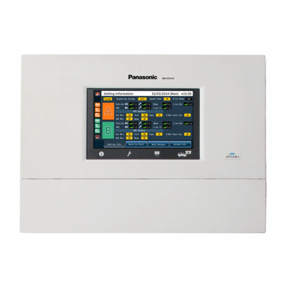
Page 16: Setting Information Screen
This unit’s settings and statuses can be confirmed on this screen. Lane mode display [Single/Dual/Tandem] Lane mode that has been set is displayed. WX-CC411: [Single] is displayed. WX-CC412: [Dual] is displayed when the tandem lane setting is OFF, and [Tandem] is displayed when it is ON. Nighttime Volume display... - Page 17 Lane A V/Det Override ON/OFF display Lane A order post microphone volume display [Outside] [V/Det Override ON/OFF] The volume level of the lane A order post microphone is The status of the lane A V/Det Override is displayed. displayed. Note Lane A kitchen microphone volume display “V/Det Override”...
-
Page 18: Password Input Screen
Description of screens Help Contact screen Password input screen The Help Contact screen appears when the [Help Contact] The password must be input for verification before operation button on the LCD display is touched. moves to the setting screen. The password input screen appears when (setting button) on the touch panel is touched. -
Page 19: Quick Operation Screen
Camera 4 screen Quick Operation screen Images from Network Camera 4 appear on this part of the screen. The Quick Operation screen appears on the LCD display when (Quick Operation button) on the touch panel is Camera 1 full-screen display button touched. -
Page 20: Related Devices
Related devices Devices related to the wireless intercom system are listed below. Center Module Belt Pack WX-CC411/WX-CC412 WX-CT420 All-In-One Headset Headset WX-CH450 WX-CH427 Battery Battery Charger WX-B3030 WX-Z3040A Wireless Repeater WX-CR470... -
Page 21: Installation Procedures
Installation procedures Deciding on where to install the Center Module Select a wall on which to mount this unit, drill a hole in it to pass the wires through, and decide where the four screws are to be positioned, as shown below. Important Ensure that the installation surface has the pull-out strength below. - Page 22 Installation procedures Mount this unit onto the four hooks of the wall mounting bracket. Look at the confirmation window (which is marked “CHECK”), and confirm that this unit fits properly into place. Check that the “ ” marks of the wall mounting bracket are visible. If they are not visible, this means that this unit has not been installed properly.
- Page 23 Use the accessory clamp to secure the power cord to the wall and attach the clamp using a screw (4.1 mm × 25 mm {5/32 inches × 63/64 inches}). [Minimum pull-out strength: 780 N {80 k f}] Screw (locally procured) 150 mm to 200 mm {5-15/16 inches to 7-7/8 inches}...
-
Page 24: Connections
Connections Opening the connector cover Press on the area indicated by and slide the connector cover down, and pull the bottom part of the cover toward you as indicated by Securing the power cord Insert the accessory power cord clamp into this unit. -
Page 25: Wiring The Euroblock Connector
Before proceeding any further, push down the position of the power cord clamp inserted into this unit, as shown in the figure below. Insert the power cord plug into the power socket of this unit, adjust the position of the power cord clamp, and secure the power cord. Wiring the Euroblock connector A detachable Euroblock connector is provided for this unit’s connectors. - Page 26 Connections Connect the wires to the Euroblock connector. Using a slot-head screwdriver, loosen the Euroblock connector screws in turn, peel off the insulating material around each of the wires, twist the conductors firmly, insert the ends of the conductors into the Euroblock connector, and tighten the Euroblock connector screws.
-
Page 27: Attaching The Connector Cover
Install the Euroblock connector, to which the wires have been connected, in this unit. Note Insert the Euroblock connector firmly into this unit. Attaching the connector cover Slide the connector cover from below, and attach it to this unit. Note Attach the connector cover securely to this unit. -
Page 28: Examples Of Connections
Connections Examples of connections Lane A External Order post device Expanded Sensors vehicle Refrigerator Kitchen monitor detector Kitchen Cash register, Microphone microphone etc. Vehicle detector Speaker Kitchen speaker (8 ) (8 ) Drive-thru lane A Network Cameras Lane B (WX-CC412 only) Order post Expanded vehicle... -
Page 29: Screen Operations
Screen operations Note Basic screen operations The LCD display is easily scratched, so always This section describes basic screen operations. perform the operations involving this display using For details on how to operate the unit and select its settings, one finger. refer to the “Operating Instructions <Setup Instructions>”... -
Page 30: Inputting Characters
Screen operations Inputting characters Inputting the date and time Use the keys on the keyboard to input the characters when Input the date and time—the time may involve using Daylight a password or an address is to be input. Saving Time. Input character display area The characters that have been input are displayed. -
Page 31: Operating Procedures
Operating procedures Basic operations ID Registration To talk or page using an All-In-One Headset or Belt Pack, TALK: Talking with the customers its ID must be registered. This function enables two-way conversations between the For ID registration, set the Center Module to ID store personnel who are wearing All-In-One Headsets or registration mode, and proceed with the registration by Belt Packs and the customer at the order post. - Page 32 Operating procedures Touch [Headsets] button, and then the [ID Press the [T1] button on the All-In-One Registration] button. Headset or Belt Pack. The ID registration screen appears. The All-In-One Headset or Belt Pack searches for a Center Module that is in ID registration mode. The “Connecting center module A”...
-
Page 33: Convenient Functions (Other Functions)
Speed Team Convenient Functions (Other Functions) “Speed Team operation” refers to a mode of operation in which, at busy times when there are more vehicles than the Auto-TALK-Lock lanes can accommodate, normal operation is suspended, the vehicle detectors are shut off, and the store personnel This function enables the All-In-One Headset or Belt Pack of go directly to the customers in their vehicles to take their pre-determined store personnel to automatically enter talk... - Page 34 Operating procedures To release Speed Team operation, touch the Cross Beep (WX-CC412 only) [OFF] button for [Speed Team] on the screen in “Cross Beep” is a function that enables a beep tone to be step 2. heard from the All-In-One Headsets or Belt Packs when a In the All-In-One Headsets or Belt Packs, the customer approaches the order post of the other lane.
- Page 35 V/Det Override Talk/page release “V/Det Override” is a function that sets the vehicle detectors The talk (or page) status of an All-In-One Headset or Belt virtually to ON and keeps both the order post microphone Pack is forcibly released. and speaker in the ON setting. Touch (Quick Operation button) on the Touch...
-
Page 36: Troubleshooting
Troubleshooting Check the following before requesting repair. Consult your sales shop if these measures do not resolve a problem, if symptoms not listed here occur, or if you have a question related to engineering. Symptom Cause/solution Reference pages No communication between Is the power cord connected securely to the AC input terminal the order post, Belt Packs of this unit and to the power outlet? -
Page 37: Specifications
Effective pixels WVGA: 800 (H) × 480 (V) Back light Type 7.8 Type Touch panel Technology Resistive type Audio & Video Interface 1 (WX-CC411) Number of channels 2 (WX-CC412) General Frequency characteristic 300 Hz to 3 kHz Technology Electric balanced Connector... - Page 38 +6 dBV Technology Unbalanced, Mono Connector Euroblock connector LINE OUT Rated output –14 dBV Maximum output +6 dBV Device Interface 1 (WX-CC411) Number of channels 2 (WX-CC412) Technology Photo-coupler AUX MIC CNT, COM (INPUT) Open voltage Short current 2 mA Connector...
-
Page 39: Licenses
Licenses This unit contains thttpd, NetBSD, OpenSSL Project, Arcfour and MD5 message-digest algorithm software licensed by third parties, and use of this software has been granted under the conditions stated below. LICENSE ISSUES This product uses some parts of thttpd, NetBSD, OpenSSL Project, Arcfour, MD5 message-digest algorithm. The use of parts described above are licensed under the conditions below. - Page 40 Licenses < isys_pl_stdio.c > Copyright (c) 1990 The Regents of the University of California. All rights reserved. This code is derived from software contributed to Berkeley by Chris Torek. Redistribution and use in source and binary forms, with or without modification, are permitted provided that the following conditions are met: 1.
- Page 41 THIS SOFTWARE IS PROVIDED BY THE REGENTS AND CONTRIBUTORS ''AS IS'' AND ANY EXPRESS OR IMPLIED WARRANTIES, INCLUDING, BUT NOT LIMITED TO, THE IMPLIED WARRANTIES OF MERCHANTABILITY AND FITNESS FOR A PARTICULAR PURPOSE ARE DISCLAIMED. IN NO EVENT SHALL THE REGENTS OR CONTRIBUTORS BE LIABLE FOR ANY DIRECT, INDIRECT, INCIDENTAL, SPECIAL, EXEMPLARY, OR CONSEQUENTIAL DAMAGES (INCLUDING, BUT NOT LIMITED TO, PROCUREMENT OF SUBSTITUTE GOODS OR SERVICES;...
- Page 42 Licenses «OpenSSL» This product includes software developed by the OpenSSL Project for use in the OpenSSL Toolkit (http://www.openssl.org/). < md32_common.h> Copyright (c) 1999-2002 The OpenSSL Project. All rights reserved. Redistribution and use in source and binary forms, with or without modification, are permitted provided that the following conditions are met: 1.
- Page 43 THIS SOFTWARE IS PROVIDED BY ERIC YOUNG ''AS IS'' AND ANY EXPRESS OR IMPLIED WARRANTIES, INCLUDING, BUT NOT LIMITED TO, THE IMPLIED WARRANTIES OF MERCHANTABILITY AND FITNESS FOR A PARTICULAR PURPOSE ARE DISCLAIMED. IN NO EVENT SHALL THE AUTHOR OR CONTRIBUTORS BE LIABLE FOR ANY DIRECT, INDIRECT, INCIDENTAL, SPECIAL, EXEMPLARY, OR CONSEQUENTIAL DAMAGES (INCLUDING, BUT NOT LIMITED TO, PROCUREMENT OF SUBSTITUTE GOODS OR SERVICES;...
- Page 44 Licenses Copyright remains Eric Young's, and as such any Copyright notices in the code are not to be removed. If this package is used in a product, Eric Young should be given attribution as the author of the parts of the library used. This can be in the form of a textual message at program startup or in documentation (online or textual) provided with the package.
- Page 45 Arcfour Copyright (c) April 29, 1997 Kalle Kaukonen. All Rights Reserved. Redistribution and use in source and binary forms, with or without modification, are permitted provided that this copyright notice and disclaimer are retained. THIS SOFTWARE IS PROVIDED BY KALLE KAUKONEN AND CONTRIBUTORS ''AS IS'' AND ANY EXPRESS OR IMPLIED WARRANTIES, INCLUDING, BUT NOT LIMITED TO, THE IMPLIED WARRANTIES OF MERCHANTABILITY AND FITNESS FOR A PARTICULAR PURPOSE ARE DISCLAIMED.
-
Page 46: Consignes De Sécurité
VERSION FRANÇAISE (FRENCH VERSION) Consignes de sécurité DÉCLARATION DE LA COMMISSION FÉDÉRALE DES TÉLÉCOMMUNICATIONS (FCC) SUR LES INTERFÉRENCES Cet équipement a été testé et déclaré conforme aux spécifications de la Classe A des appareils numériques, suivant le chapitre Part 15 des Règles FCC. Ces limites sont prévues pour assurer une protection suffisante contre les interférences nuisibles dans une installation commerciale. -
Page 47: Instructions De Sécurité Importantes
Consignes de sécurité Pour Canada ICES-003 ATTENTION: CAN ICES-3(A)/NMB-3(A) Risque d’explosion si la batterie n’est pas correctement remplacée. Ne remplacer qu’avec une batterie de type identique ou équivalent. Les présentes instructions de service ne doivent être Pour Canada utilisées que par le personnel de service qualifié. Pour CNR-Gen réduire les risques de décharge électrique, n’effectuer Conformément à... - Page 48 Sommaire Consignes de sécurité ........... 46 Commandes sur écran ........... 73 Commandes de base sur écran ........73 Avant utilisation .............. 49 Saisie des paramètres ..........73 Préface ................. 49 Saisie des caractères ........... 74 Caractéristiques dominantes ........49 Saisie de la date et de l’heure ........74 Schéma du système ............
-
Page 49: Avant Utilisation
Caractéristiques dominantes Le WX-CC411 est conçu pour l’utilisation en allée simple dans les installations de service au volant, et le WX-CC412 pour l’utilisation en allée double. La stabilité de la communication est assurée par l’utilisation d’un système conforme à la norme DECT* pour bande de fréquence 1,9 GHz, qui permet la transmission claire et distincte de la voix des membres du personnel et des clients, même... -
Page 50: Avant Utilisation
Ce système prend en charge les opérations suivantes pour les clients du service au volant. Allée simple Les opérations effectuées dans un environnement où une seule borne de commande est installée sont appelées opérations d’ “allée simple”. Ces opérations d’allée sont prises en charge par le WX-CC411. Bonjour BORNE DE COMMANDE FENÊTRE Allée double... -
Page 51: Allée Tandem
Web d’Adobe et l’installer. Important Télécharger le “Manuel d’utilisation <Instructions de configuration/Guide d’utilisation du navigateur>” depuis la page d’accueil indiquée ci-dessous. http://www.panasonic.com/business/POS-drive-through/manuals.asp Accessoires standard Cordon d’alimentation ............1 Pince (pour fixer le cordon d’alimentation au mur) ....1 Support de montage mural ..........1... -
Page 52: Abréviations
BUT PARTICULIER OU NON-INFRACTION DES DROITS D’UN TIERS. Déni de la garantie EN AUCUN CAS Panasonic Corporation NE SERA TENU POUR RESPONSABLE POUR TOUTE PARTIE OU TOUTE PERSONNE, À L’EXCEPTION DU REMPLACEMENT OU D’UNE MAINTENANCE RAISONNABLE DE CE PRODUIT POUR LES CAS CITÉS, INCLUS MAIS NON LIMITÉS À... -
Page 53: Mesures De Précaution
Mesures de précaution Cesser immédiatement l’utilisation si l’appareil dégage Précautions d’utilisation de la fumée, une chaleur excessive ou une odeur anormale. Ces situations comportent un risque d’incendie L’appareil est destiné à une utilisation seulement interne. ou de décharge électrique. Le cas échéant, débrancher Il ne peut pas s’utiliser en extérieur. -
Page 54: Précautions D'installation
à la masse. suivant les instructions du Manuel d’utilisation. Paramétrage de l’heure Panasonic n’assume aucune responsabilité en cas de Avant d’utiliser cet appareil, il faut paramétrer l’heure. Au sujet dommages corporels ou matériels résultant de pannes de la façon de paramétrer l’heure, se reporter au Manuel... -
Page 55: Principaux Organes De Commande Et Fonctions
Principaux organes de commande et fonctions Panneau avant Affichage ACL Il s’agit d’un affichage ACL couleur de type 7. Il indique l’état de fonctionnement de l’appareil et des détails sur les opérations et paramètres. Écran tactile Il s’agit d’un écran tactile de type 7,8. Il sert à commander cet appareil. Couvercle de bornier C’est ici que se trouve l’... -
Page 56: Bornier
Principaux organes de commande et fonctions Bornier Borne d’entrée d’alimentation [AC IN] Entrée de détecteur de véhicule d’allée A [VDET] Brancher le cordon d’alimentation en accessoire sur cette Elle se connecte au détecteur de véhicule installé sur borne. Après l’avoir branché, fixer le cordon à l’aide de la l’allée A. -
Page 57: Panneau Latéral
Sortie de commande externe [DEVICE] Cette sortie de commande externe est utilisée pour les alertes. Ce connecteur, qui utilise les paramètres de cet appareil, est commandé en réponse aux signaux d’alerte reçus des casques d’écoute tout-en-un ou modules de commande pour ceinture et des signaux provenant de l’entrée d’alerte. -
Page 58: Écran
Ce bouton sert à afficher les paramètres et états. Ce bouton sert à afficher les images des caméras en réseau (Se reporter à “Écran Informations sur paramétrages”, p.60.) Panasonic enregistrées. (Se reporter à “Écran de contrôle des caméras”, p.62.) Bouton de paramétrage Bouton Opération express... -
Page 59: Description Des Écrans
Description des écrans Affichage du mode de voix (allée B) Écran de base S’affiche en vert pendant que le personnel du magasin L’écran de base qui apparaît sur l’affichage ACL est décrit parle au client de l’allée B. ci-dessous. Affichage d’INTER. (allée B) S’affiche en vert pendant que les employés du personnel du magasin sur l’allée B parlent entre eux. -
Page 60: Écran Informations Sur Paramétrages
Les paramètres et états de cet appareil Le mode d’allée paramétré s’affiche. peuvent être vérifiés sur cet écran. WX-CC411 : [Simple] s’affiche. WX-CC412 : [Double] s’affiche lorsque le paramètre d’allée tandem est NON, et [Tandem] lorsqu’il est OUI. -
Page 61: Écran Alerte Sécurité
Affichage OUI/NON de Détect./V. désactivé Affichage du volume du microphone de la borne de commande d’allée A [Ext.] d’allée A [Dét/V désact. OUI/NON] Le niveau du volume du microphone de la borne de L’état de Détect./V. désactivé de l’allée A s’affiche. commande d’allée A s’affiche. -
Page 62: Écran De Saisie Du Mot De Passe
Description des écrans Écran Aide-ressource Écran de saisie du mot de L’écran Aide-ressource apparaît lorsque l’on appuie sur le passe bouton [Aide-ressource] sur l’affichage ACL. Le mot de passe doit être saisi pour vérification avant que l’on puisse passer à l’écran de paramétrages. L’écran de saisie du mot de passe apparaît lorsque l’on appuie sur (bouton de paramétrage). -
Page 63: Écran Opération Express
Écran de caméra 4 Écran Opération express L’image de la caméra en réseau 4 apparaît dans cette partie de l’écran. L’écran Opération express apparaît sur l’affichage ACL lorsque l’on appuie sur (bouton Opération express) Bouton d’affichage plein écran de la caméra 1 sur l’écran tactile. -
Page 64: Dispositifs Associés
Dispositifs associés Les dispositifs associés au système d’intercommunication sans fil sont indiqués ci-dessous. Module central Module de commande pour ceinture WX-CC411/WX-CC412 WX-CT420 Casque d’écoute tout-en-un Casque d’écoute WX-CH450 WX-CH427 Pile Chargeur de pile WX-B3030 WX-Z3040A Répéteur sans fil WX-CR470... -
Page 65: Procédures D'installation
Procédures d’installation Choix de l’emplacement d’installation du module central Choisir un mur pour le montage de l’appareil, percer un trou dans le mur pour y faire passer les câbles, et choisir l’emplacement des quatre vis, tel qu’illustré ci-dessous. Important S’assurer que la surface d’installation a la résistance à l’arrachement indiquée ci-dessous. Installation Monter l’appareil à... - Page 66 Procédures d’installation Monter l’appareil sur les quatre crochets du support de montage mural. Vérifier sur la fenêtre de confirmation (marquée “CHECK”) que l’appareil est mis en place correctement. S’assurer que les marques “ ” du support de montage mural sont visibles.
- Page 67 Utiliser la pince en accessoire pour fixer le cordon d’alimentation au mur, et fixer la pince à l’aide de la vis (4,1 mm × 25 mm {5/32 po × 63/64 po}). [Résistance minimale à l’arrachement : 780 N {80 k f}] Vis (à...
-
Page 68: Connexions
Connexions Ouverture du couvercle de connecteurs Appuyer sur la zone indiquée par et faire glisser le couvercle de connecteurs vers le bas, puis tirer vers soi la partie inférieure du couvercle indiquée par Fixation du cordon d’alimentation Insérer la pince de cordon d’alimentation en accessoire dans l’appareil. -
Page 69: Câblage Du Connecteur Euroblock
Avant de poursuivre, abaisser la pince de cordon d’alimentation insérée dans l’appareil, tel qu’illustré ci-dessous. Insérer la fiche du cordon d’alimentation dans la prise d’alimentation de l’appareil, ajuster la position de la pince de cordon d’alimentation, et fixer le cordon d’alimentation. Câblage du connecteur Euroblock Un connecteur Euroblock amovible est fourni pour les connecteurs de l’appareil. - Page 70 Connexions Connecter les câbles au connecteur Euroblock. À l’aide d’un tournevis plat, desserrer l’une après l’autre les vis du connecteur Euroblock, détacher le matériau isolant autour de chaque câble, torsader fermement les conducteurs, insérer l’extrémité des conducteurs dans le connecteur Euroblock, et serrer les vis du connecteur Euroblock.
-
Page 71: Fixation Du Couvercle De Connecteurs
Installer le connecteur Euroblock, auquel les câbles ont été connectés, dans l’appareil. Remarque Insérer fermement le connecteur Euroblock dans l’appareil. Fixation du couvercle de connecteurs Faire glisser le couvercle de connecteurs par le bas, et le fixer à l’appareil. Remarque Fixer le couvercle de connecteurs fermement à... -
Page 72: Exemples De Connexion
Connexions Exemples de connexion Allée A Périphérique Borne de commande externe Détecteur Détecteurs de véhicule Réfrigérateur Moniteur de cuisine Microphone étendu Caisse Microphone de cuisine enregistreuse, etc. Détecteur de véhicule Concentrateur Haut-parleur Haut-parleur de (8 ) cuisine (8 ) Allée A de service au volant Caméras en réseau Ordinateur Allée B (uniquement avec le WX-CC412) -
Page 73: Commandes Sur Écran
Commandes sur écran Remarque Commandes de base sur écran Comme l’affichage ACL se raye facilement, toujours Cette section décrit les commandes de base sur écran. effectuer les commandes avec un doigt. Pour plus de détails sur l’utilisation de l’appareil et Ne pas utiliser un stylo à... -
Page 74: Saisie Des Caractères
Commandes sur écran Saisie des caractères Saisie de la date et de l’heure Lorsqu’il faut saisir un mot de passe ou une adresse, utiliser Saisir la date et l’heure — la saisie de la date peut impliquer les boutons du clavier pour saisir les caractères. l’utilisation de l’heure avancée. -
Page 75: Procédures D'utilisation
Procédures d’utilisation Opérations de base Enregistrement ID Pour pouvoir utiliser le mode de voix ou VOIX : Pour parler aux clients d’intercommunication au moyen d’un casque d’écoute Cette fonction sert aux conversations bidirectionnelles tout-en-un ou d’un module de commande pour ceinture, il entre les membres du personnel du magasin qui portent faut que son identifiant (ID) soit enregistré. - Page 76 Procédures d’utilisation Appuyer sur le bouton [Casques d’écoute], Appuyer sur le bouton [POWER] tout en puis sur le bouton [Enregistrement ID]. maintenant enfoncés les boutons [T1] et [T2] sur le casque d’écoute tout-en-un ou le L’écran Enregistrement ID apparaît. module de commande pour ceinture. Le casque d’écoute tout-en-un ou le module de commande pour ceinture démarre en mode d’enregistrement ID.
- Page 77 Important Lorsque l’on enregistre l’ID de plusieurs casques d’écoute tout-en-un ou modules de commande pour ceinture, enregistrer l’ID sur un appareil à la fois. Si l’on essaie d’enregistrer l’ID de plusieurs appareils à la fois, les ID risquent de ne pas être enregistrés correctement.
-
Page 78: Fonctions Pratiques (Autres Fonctions)
Procédures d’utilisation Équipe express Fonctions pratiques (Autres fonctions) “Opération Équipe express” désigne un mode d’opération où, lorsque l’achalandage des véhicules dépasse la Verrouillage automatique pour parler aux capacité des allées, le fonctionnement normal est interrompu, les détecteurs de véhicule sont fermés et les clients membres du personnel du magasin se rendent en personne Cette fonction permet au casque d’écoute tout-en-un ou au... - Page 79 Pour annuler l’opération Équipe express, Bip trans-allée (uniquement avec le appuyer sur le bouton [NON] d’[Équipe WX-CC412) express] sur l’écran de l’étape 2. “Bip trans-allée” est une fonction qui permet d’émettre une Le message vocal “Le mode ÉQUIPE EXPRESS tonalité par les casques d’écoute tout-en-un ou modules de est désactivé”...
-
Page 80: Détect./V. Désactivé
Procédures d’utilisation Détect./V. désactivé Annulation du mode de voix ou d’intercommunication “Détect./V. désactivé” est une fonction qui sert à paramétrer les détecteurs de véhicule virtuellement sur OUI et à Cela force l’annulation de l’état de voix (ou maintenir le microphone et le haut-parleur de la borne de d’intercommunication) d’un casque d’écoute tout-en-un ou commande sur le paramètre OUI. -
Page 81: Dépannage
Dépannage Avant de faire une demande de réparation, vérifier les points suivants. Consulter le revendeur si ces mesures ne règlent pas le problème, si des symptômes non mentionnés se produisent, ou pour toute question d’ingénierie. Pages de Symptôme Origine/Solution référence Aucune communication n’est possible entre la borne de Le cordon d’alimentation est-il branché... -
Page 82: Caractéristiques Techniques
Pixels effectifs WVGA: 800 (H) × 480 (V) Rétroéclairage Type Type 7,8 Écran tactile Technologie Type résistif Interface audio et vidéo 1 (WX-CC411) Nombre de canaux 2 (WX-CC412) Généralités Caractéristique de fréquence 300 Hz à 3 kHz Technologie Équilibre électrique Connecteur... - Page 83 Dissymétrique, monaural Connecteur Connecteur Euroblock LINE OUT Sortie nominale –14 dBV Sortie maximale +6 dBV Interface de l’appareil 1 (WX-CC411) Nombre de canaux 2 (WX-CC412) Technologie Photocoupleur AUX MIC CNT, COM (ENTRÉE) Tension de circuit ouvert Courant de court-circuit 2 mA...
- Page 84 © Panasonic System Networks Co., Ltd. 2013 Fd1213-1014 PGQX1416YA Printed in China...